
Lampshade Assembly that is Assembly Quickly

Inactive Publication Date: 2016-03-10
TAIDER ELECTRIC MFR
View PDF7 Cites 0 Cited by
  • Summary
  • Abstract
  • Description
  • Claims
  • Application Information

AI Technical Summary

Benefits of technology

The present invention relates to a lampshade assembly with an improved mounting system that allows for quick and easy mounting and efficient use of energy. The mounting end of the shade is pushed towards the mounting seat, which causes the claws of the mounting seat to lock into the locking portion of the shade, allowing for secure mounting. The lampshade assembly is assembled easily and quickly, saving time and energy. Additionally, the outer surface of the shade does not have any screw bores, improving aesthetic quality. These technical effects enhance the overall performance of the lampshade assembly.

Problems solved by technology

However, it is difficult to align the screw bores of the mounting seat and the screw bores of the shade, thereby causing inconvenience to the operator in assembly of the mounting seat and the shade.
In addition, the screws are easily detached from the screw bores during the assembly process and fall down onto the ground, thereby causing inconvenience to the operator, and thereby wasting the working time.
Further, the screws are exposed outward from the shade, thereby decreasing the aesthetic quality of the lampshade assembly.

Method used


Image

  • Lampshade Assembly that is Assembly Quickly
  • Lampshade Assembly that is Assembly Quickly
  • Lampshade Assembly that is Assembly Quickly

Examples


Embodiment Construction

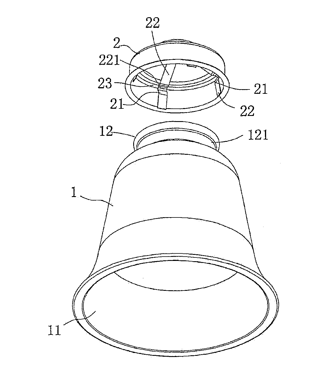
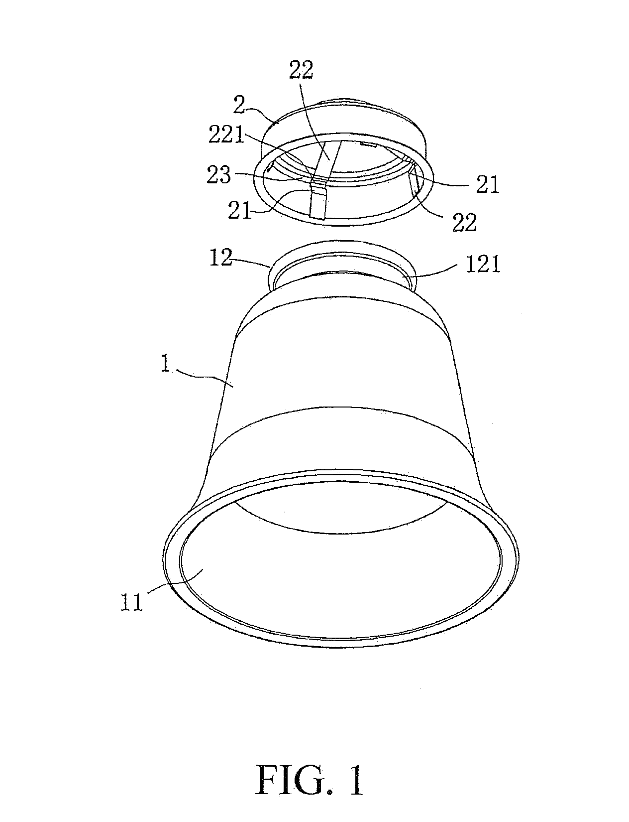
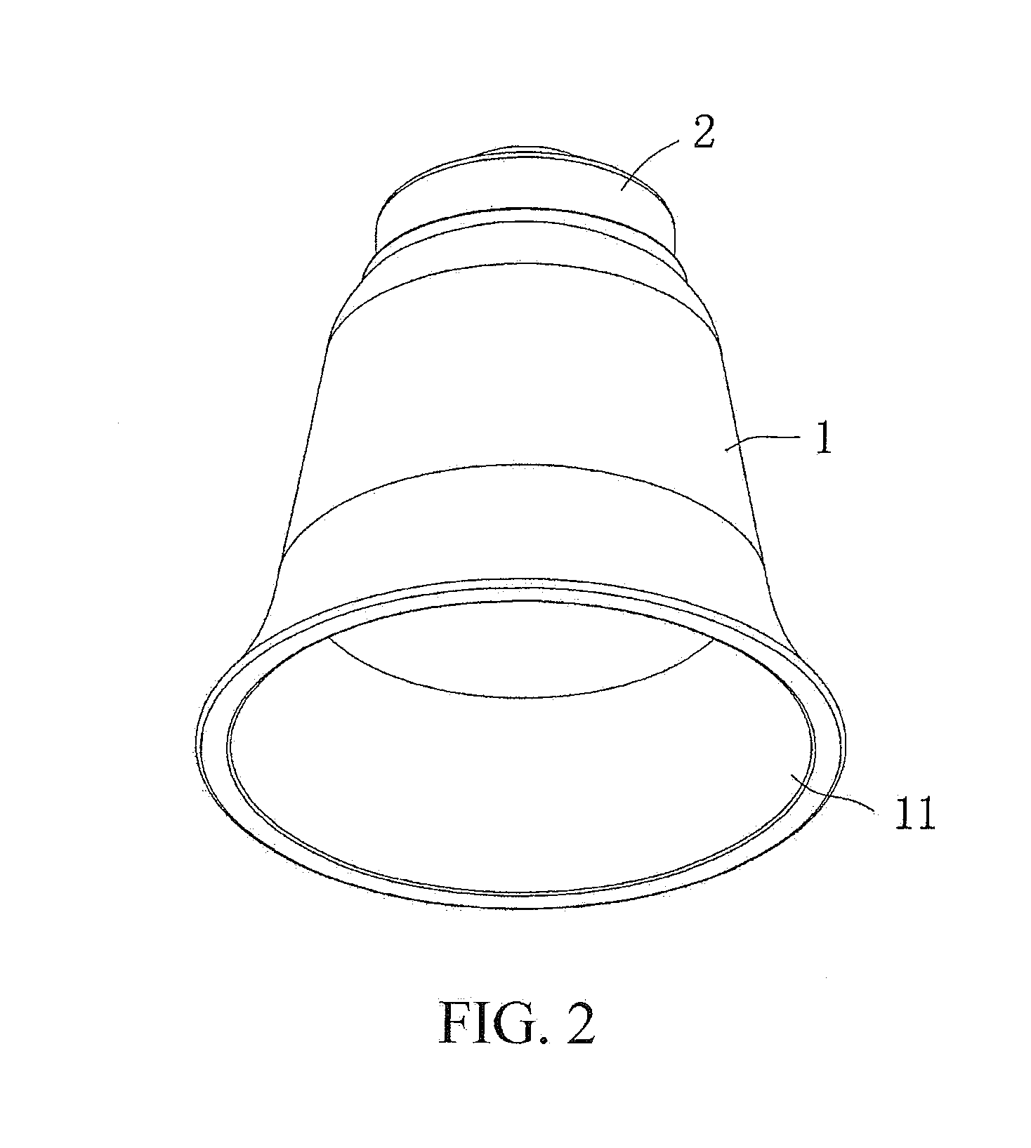
[0016]Referring to FIGS. 1 and 2, a lampshade assembly in accordance with the preferred embodiment of the present invention comprises a shade 1 and a mounting seat 2.

[0017]The shade 1 is hollow and has an open end 11 and a mounting end 12. The open end 11 of the shade 1 allows a light source to be emitted from the shade 1. The mounting end 12 of the shade 1 has an outer peripheral wall provided with a locking portion 121. In the preferred embodiment of the present invention, the locking portion 121 of the shade 1 is an annular groove to facilitate working design and assembly. Alternatively, the locking portion 121 of the shade 1 includes concave or convex portions arranged on the outer peripheral wall of the mounting end 12 of the shade 1.

[0018]The mounting seat 2 has a plurality of claws 21 movably locked onto and connected with the locking portion 121 of the shade 1 to mount the shade 1 onto the mounting seat 2. In the preferred embodiment of the present invention, the claws 21 of...


PUM


Abstract

A lampshade assembly includes a shade and a mounting seat. The shade is hollow and has an open end and a mounting end. The mounting end of the shade has an outer peripheral wall provided with a locking portion. The mounting seat has a plurality of claws movably locked onto and connected with the locking portion of the shade to mount the shade onto the mounting seat. Thus, when the mounting end of the shade is pushed toward the mounting seat, each of the claws of the mounting seat is pressed and locked into the locking portion of the shade to mount the shade onto the mounting seat.

Description

BACKGROUND OF THE INVENTION[0001]1. Field of the Invention[0002]The present invention relates to a lighting accessory and, more particularly, to a lampshade assembly for a lighting device, such as a lamp and the like.[0003]2. Description of the Related Art[0004]A conventional lampshade assembly comprises a mounting seat and a shade affixed to the mounting seat by a plurality of screws. The mounting seat has a plurality of screw bores. The shade has a plurality of screw bores. In assembly, the mounting seat is initially fixed, and the shade is then mounted on the mounting seat by the screws which are screwed through the screw bores of the mounting seat and the screw bores of the shade. However, it is difficult to align the screw bores of the mounting seat and the screw bores of the shade, thereby causing inconvenience to the operator in assembly of the mounting seat and the shade. In addition, the screws are easily detached from the screw bores during the assembly process and fall do...

Claims


Application Information

Patent Timeline
IPC IPC(8): F21V1/12F21S6/00
CPCF21S6/00F21V1/12F21V1/00F21V17/164
Inventor LIN, MING-CHI
Owner TAIDER ELECTRIC MFR
Learn More