
Fail safe aircraft monitoring and tracking

a technology for aircraft and safety, applied in the field of electronic devices, can solve the problems of inability to track aircraft using these methods, affecting the safety of aircraft, and difficult identification and tracking of particular aircraft, etc., and achieves the effect of facilitating aircraft monitoring and tracking, and enhancing monitoring and reporting

Active Publication Date: 2016-03-17
L3 TECH INC
View PDF15 Cites 48 Cited by
  • Summary
  • Abstract
  • Description
  • Claims
  • Application Information

AI Technical Summary

Benefits of technology

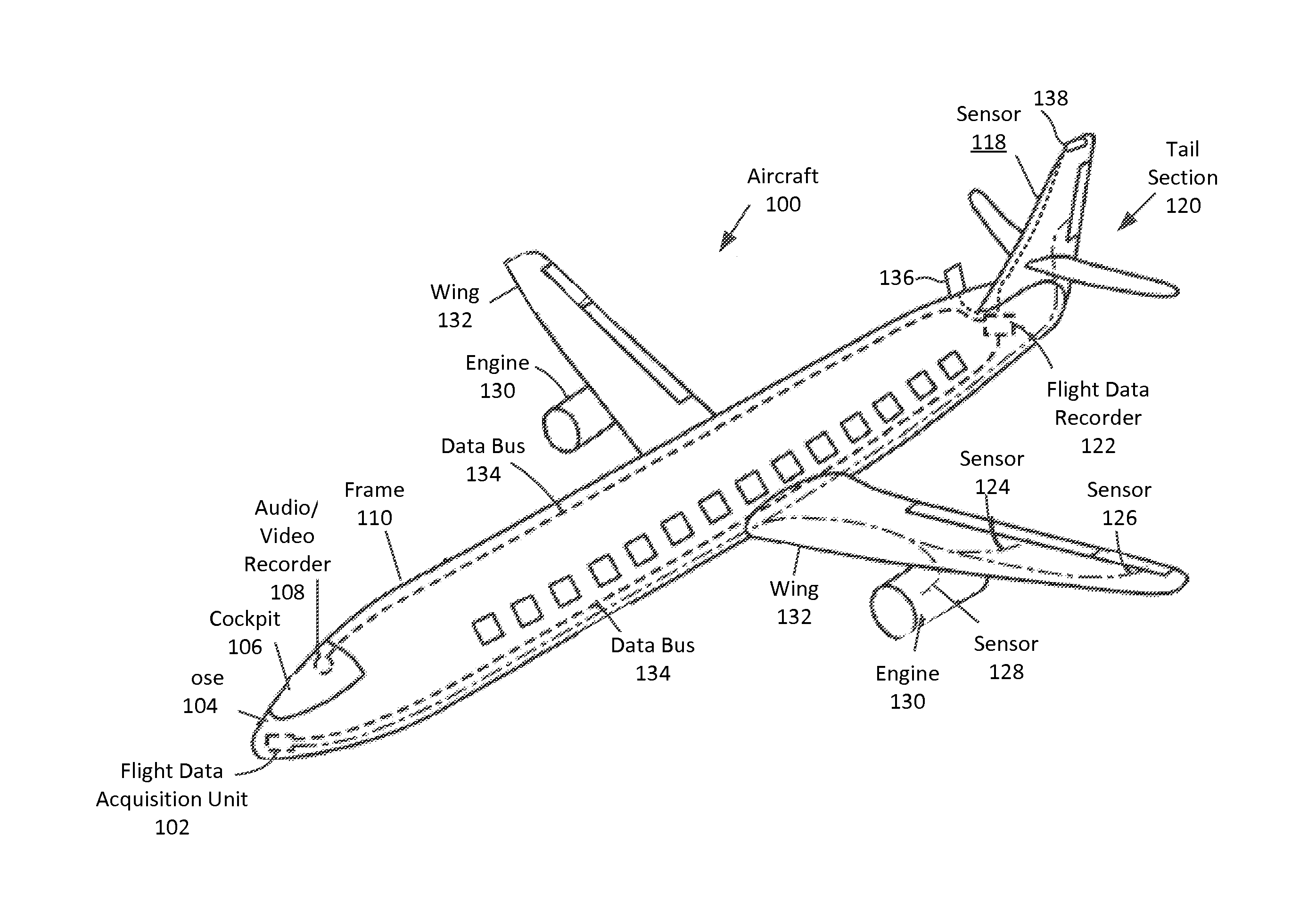
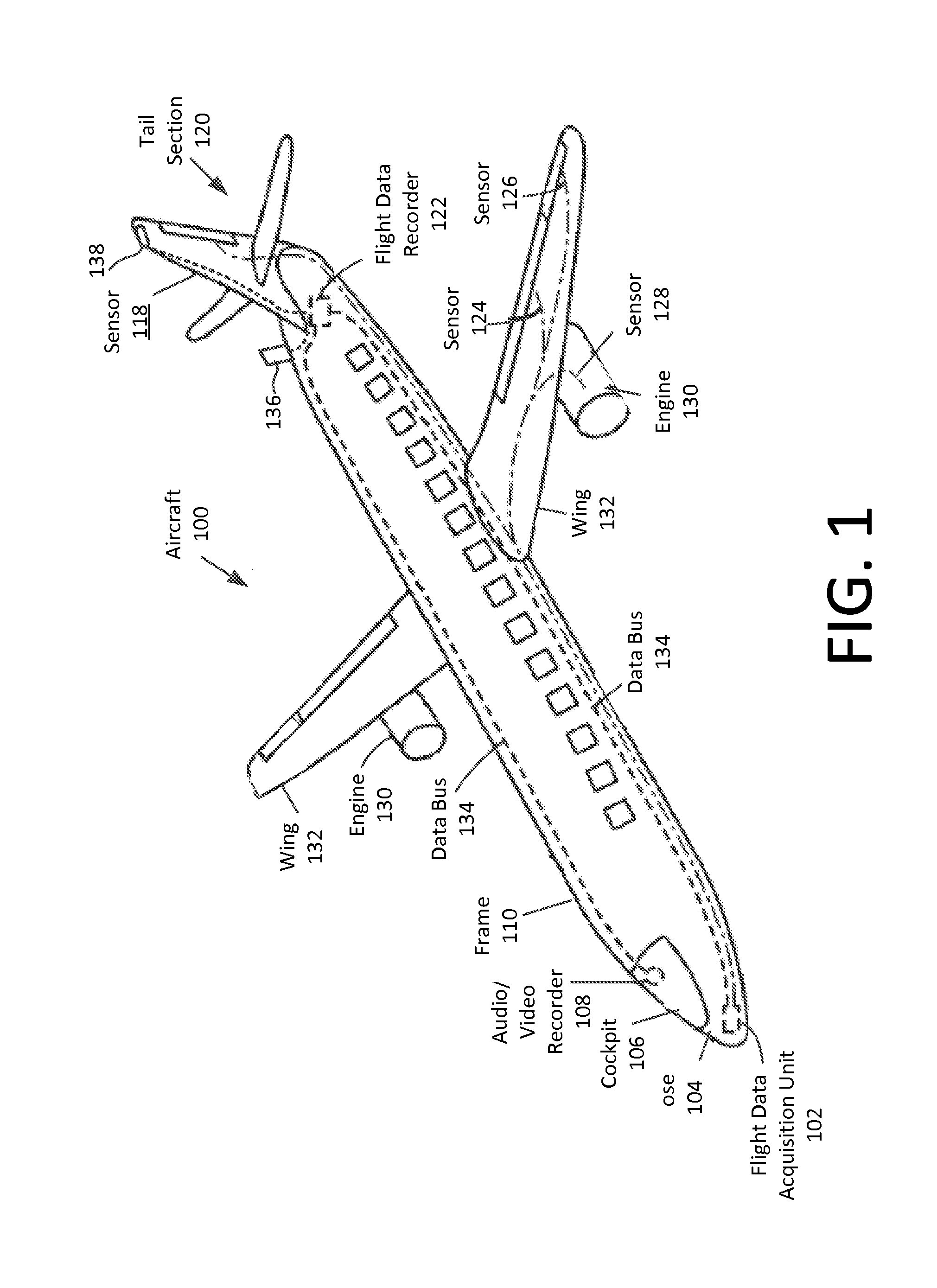
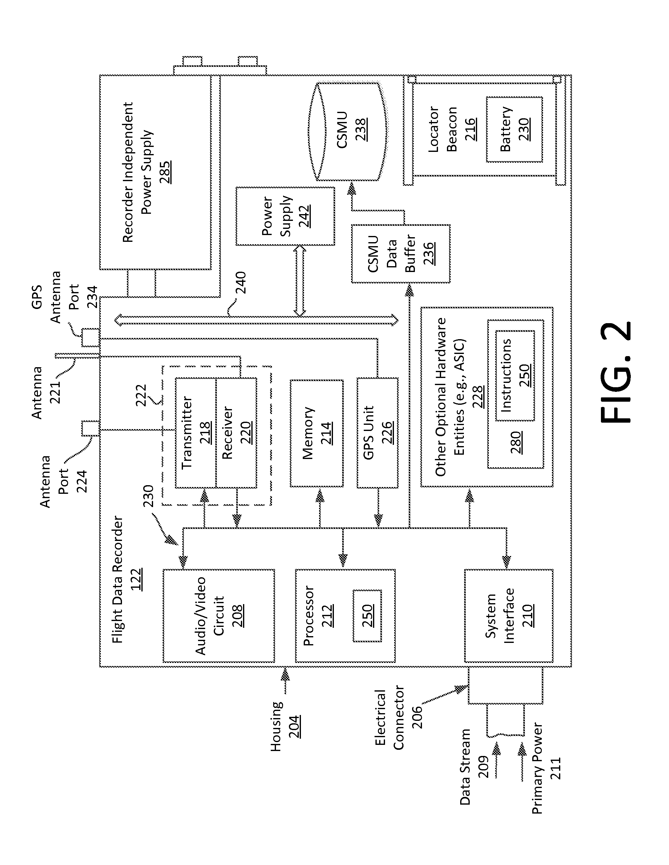
This patent describes a system for monitoring and tracking an aircraft's flight data during flight. The system includes a flight data recorder and a wireless transmitter controlled by the flight data recorder. The wireless transmitter can communicate with a remote receiving device outside the aircraft to send selected aircraft data in case of an exceptional condition. This ensures that the flight crew cannot disable the wireless transmissions of selected aircraft data during flight. The system also includes an enhanced monitoring and reporting system that can wirelessly communicate with the remote receiving device in case of an exceptional condition. The technical effect of this patent is to provide a reliable and efficient means of monitoring and tracking an aircraft's flight data during flight.

Problems solved by technology

Notably, once an aircraft is more than about 150 miles from the nearest primary and / or secondary radar station, the ability to track the aircraft using these methods is greatly diminished or non-existent.
Primary radar can identify the presence and position of aircraft, but without the secondary radar information, identification and tracking of particular aircraft can be very difficult in a crowded air space.
However, this GPS information is not commonly broadcast by the aircraft and is not generally available to ground stations or air traffic controllers using current systems.
At least one operator of low earth orbiting (LEO) satellites has proposed placing ADS-B receivers on such satellites with the goal of facilitating global, real-time aircraft surveillance But these systems are relatively expensive for aircraft operators to use due to the substantial amount of data which must be communicated through the satellite-based communication system.
Still, most systems onboard an aircraft can be selectively disabled by the flight crew.
These systems can be disabled by means of cockpit controls and / or by circuit breakers which control the primary electrical power to such systems.
As such, most aircraft systems can be disabled if the flight crew chooses to do so.

Method used


Image

  • Fail safe aircraft monitoring and tracking
  • Fail safe aircraft monitoring and tracking
  • Fail safe aircraft monitoring and tracking

Examples


tray embodiment

[0053]Referring now to FIG. 4, there is shown an alternative embodiment of the inventive arrangements, in which a conventional an FDR 422 is mounted in an avionics tray 400. In the embodiment shown in FIG. 4, certain monitoring and tracking components are incorporated into a chassis or housing defined by the avionics tray 400 to define an enhanced monitoring and reporting (EMR) system 401. The EMR system shown in FIG. 4 can include more or less components than those shown. However, the components shown are sufficient to disclose an illustrative embodiment implementing the present invention. Accordingly, the hardware architecture of FIG. 4 represents one possible embodiment of the inventive arrangements, but it should be understood that the invention is not limited in this regard.

[0054]As shown in FIG. 4, a conventional FDR 422 is disposed in an avionics tray 400. For example, the avionic tray 400 shown in FIG. 4 can be configured so that it is compatible with a certain aviation indu...


PUM


Abstract

Flight data recorder receives from an aircraft a data stream specifying values for flight data parameters while an aircraft is in flight. The flight data recorder stores the values in a crash survivable non-volatile memory unit of the flight data recorder. The flight data recorder determines an occurrence during flight of an exception condition based on an evaluation of at least one exception parameter. Responsive to determining the occurrence of the exception condition, the flight data recorder wirelessly communicates selected aircraft data to a remote location external of the aircraft using a wireless transmitter under the exclusive control of the flight data recorder.

Description

BACKGROUND OF THE INVENTION[0001]1. Statement of the Technical Field[0002]The inventive arrangements relate to electronic devices, and more particularly to systems and methods for monitoring aircraft.[0003]2. Description of the Related Art[0004]Commercial and civil aviation aircraft are closely monitored and tracked by authorities and industry participants for reasons of safety, air traffic control and maintenance purposes. A variety of different techniques and methods have been developed and are currently in use to perform such monitoring. Conventional practice is to use two separate radar systems for purposes of air traffic control. These include a primary radar system and a secondary radar system. Primary radar systems detect pulses of electromagnetic energy which are reflected off of remote aircraft to determine the approximate position of such aircraft. Because such systems operate by using the aircraft body as a passive reflector of electro-magnetic energy, they do not require...

Claims


Application Information

Patent Timeline
Patent Type & Authority Applications(United States)
IPC IPC(8): B64D45/00G01C21/14G08G5/00
CPCB64D45/00B64D2045/0065G08G5/0013G01C21/14G08G5/0021G08G5/0056G07C5/008G07C5/085
Inventor SCHMUTZ, THOMAS R.CARRO, EDUARDO M.NEMAT, AYAZREILLY, SEAN P.
Owner L3 TECH INC
Learn More