Tube bender

a tube bender and tube technology, applied in the field of tubes, can solve the problems of large size of the tube bender, time-consuming and energy-consuming tube bender, complex structure, etc., and achieve the effect of convenient and economical use, less energy, and simple structur

Inactive Publication Date: 2016-03-31
CHIEH YU CHENG
View PDF2 Cites 0 Cited by
  • Summary
  • Abstract
  • Description
  • Claims
  • Application Information

AI Technical Summary

Benefits of technology

[0007]The major object of the present invention is to provide a tube bender which allows a user to bend a tube with less energy. In addition, the tube bender has a simple structure for the user to carry around and use, and the tube bender can be assembled and disassembled in accordance with various requirements. When a member is damaged, the user only needs to replace the damaged member; therefore, it is convenient and economical for the user to use the tube bender.

Problems solved by technology

However, this type of tube benders are usually used to produce bended tubes in the same dimension in a large number, and this type of tube benders are too large to be carried around and have complex structures.
However, this type of tube bender is energy-consuming and time-consuming

Method used


Image

  • Tube bender
  • Tube bender
  • Tube bender

Examples


Embodiment Construction

[0015]The present invention will be clearer from the following description when viewed together with the accompanying drawings, which show, for purpose of illustrations only, the preferred embodiment in accordance with the present invention.

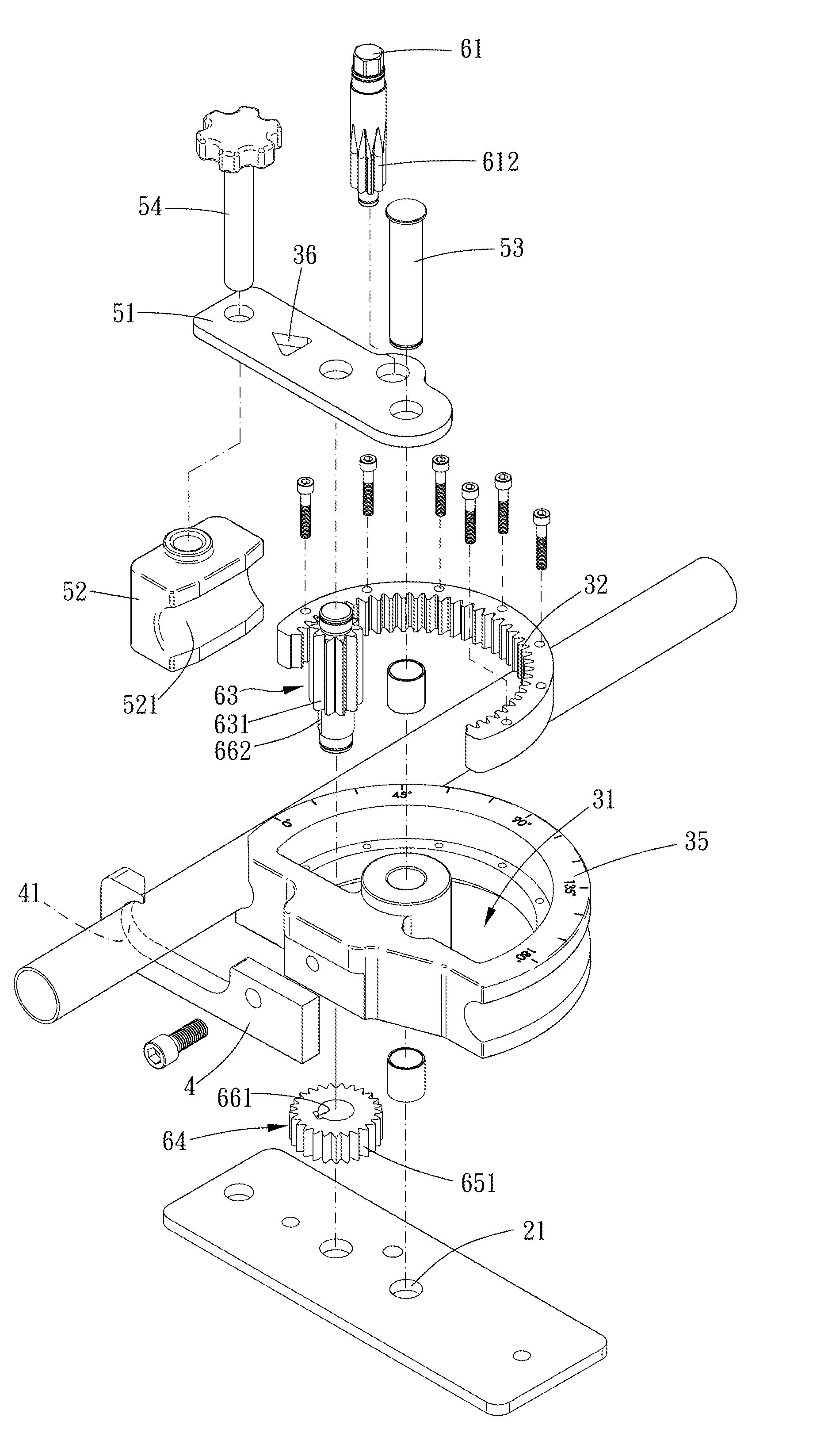
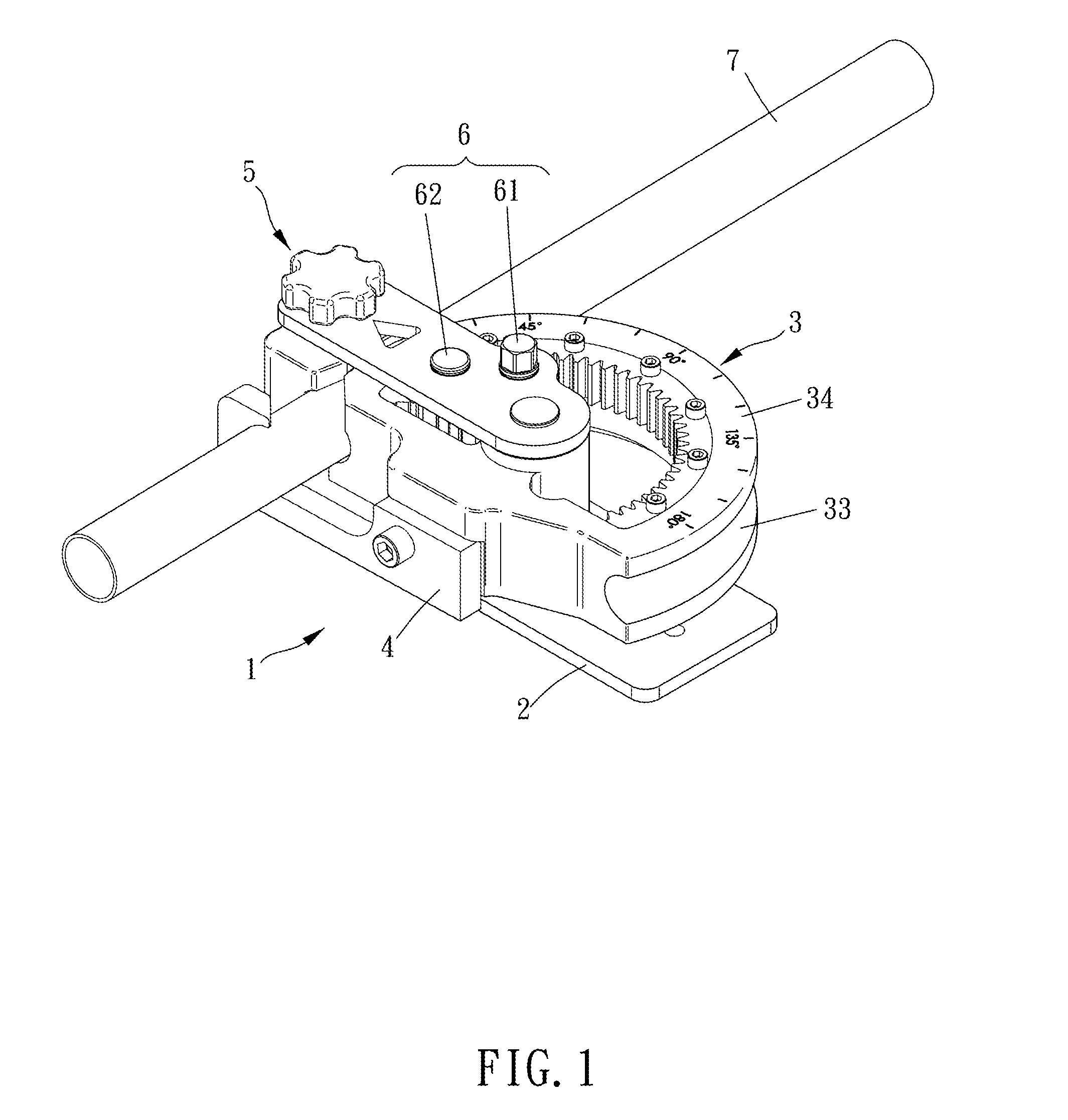
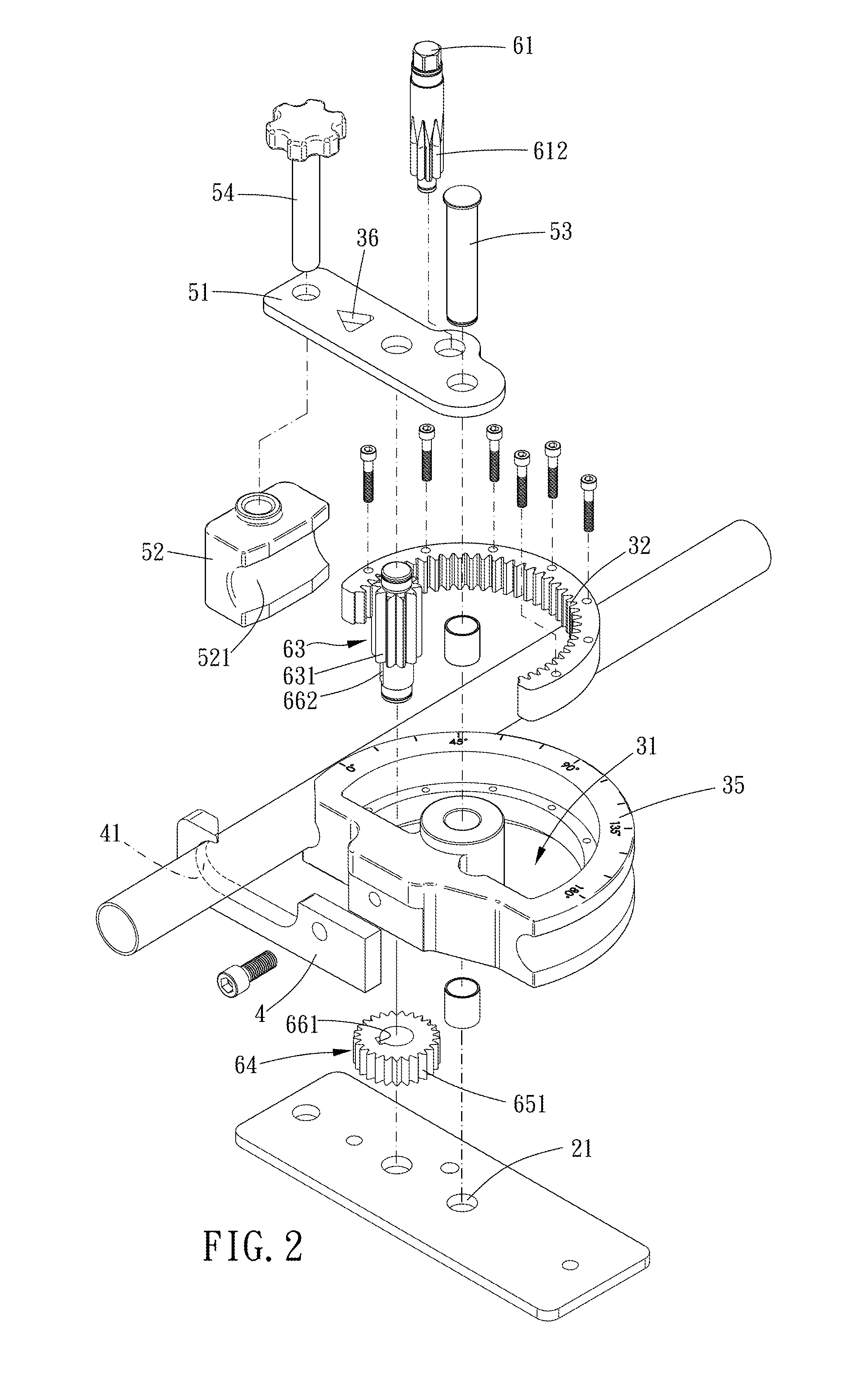
[0016]Please refer to FIGS. 1 to 6 for a preferred embodiment of the present invention. A tube bender 1 includes a base 2, a rotatable member 3, an abutting assembly 5 and a gear assembly 6.

[0017]The base 2 has a pivot portion 21. The rotatable member 3 is pivoted to the pivot portion 21 and defines an inner space 31, and the rotatable member 3 has a rack portion 32, a first arched groove 33 and a holding portion 4. The rack portion 32 archedly extends around the pivot portion 21 and located within the inner space 31. The first arched groove 33 archedly extends around the pivot portion 21 on an outer circumferential surface of the rotatable member 3. The holding portion 4 has a holding recess 41 for a tube member 7 to abut thereagainst. The abutt...


PUM

PropertyMeasurementUnit
angleaaaaaaaaaa
angleaaaaaaaaaa
energy-consumingaaaaaaaaaa

Abstract

A tube bender is provided. A rotatable member is pivoted to a base, defines an inner space and has a rack portion extending around the pivot portion within the inner space, a first arched groove archedly extending around the pivot portion and a holding portion having a holding recess for a tube. An abutting assembly has an arm portion connected with the base and an abutting chunk assembled to the arm portion. A gear assembly includes a driving assembly for being driven by a driving tool and a rotating assembly which is pivoted to the base and rotatably connected with the driving assembly. The driving assembly is pivoted to the arm portion and non-coaxially arranged with the rotating assembly, and the rotating assembly has a first toothed portion meshed with the rack portion and a driven portion meshed with the driving assembly.

Description

BACKGROUND OF THE INVENTION[0001]1. Field of the Invention[0002]The present invention relates to a bender, and more particularly to a tube bender.[0003]2. Description of the Prior Art[0004]Usually, when arranging pipelines, non-straight tube members are needed in various environments; therefore, it is necessary to use a bender to bend a straight tube member. Such tube benders are disclosed in TWI356740, TWI425989 and TWI409112. However, this type of tube benders are usually used to produce bended tubes in the same dimension in a large number, and this type of tube benders are too large to be carried around and have complex structures.[0005]Another type of tube benders as disclosed in TW161436 and TWM283695 are convenient to be carried around and can be driven by human power. However, this type of tube bender is energy-consuming and time-consuming[0006]The present invention has arisen to mitigate and / or obviate the afore-described disadvantages.SUMMARY OF THE INVENTION[0007]The major...

Claims


Application Information

Patent Timeline
Patent Type & Authority Applications(United States)
IPC IPC(8): B21D7/022
CPCB21D7/022B21D7/063B21D7/024
Inventor CHUANG, SHU-MEI
Owner CHIEH YU CHENG
Why Eureka
Try Eureka