Illuminator

a technology of illumination and front plate, applied in the field of illumination, can solve problems such as uneven brightness of the front plate, and achieve the effect of reducing uneven brightness

Active Publication Date: 2016-03-31
HONDA MOTOR CO LTD +1
View PDF7 Cites 10 Cited by
  • Summary
  • Abstract
  • Description
  • Claims
  • Application Information

AI Technical Summary

Benefits of technology

[0006]In view of the above, an object of the present invention is to provide a band of uniform emitted light with reduced unevenness in brightness.

Problems solved by technology

Unfortunately, the light emitted from the LEDs has high directional characteristics, and a part, in front of each reflector, of the front plate is more luminous than parts, in front of areas between the reflector and reflectors on both sides of the reflector, leading to unevenness in brightness in the front plate.

Method used


Image

  • Illuminator
  • Illuminator
  • Illuminator

Examples


Embodiment Construction

[0018]An embodiment to carry out the present invention will now be described below with reference to the drawings. The embodiment described below includes various limitations that are technically preferable to carry out the present invention. The technical scope of the present invention is not limited to the embodiment and the drawings.

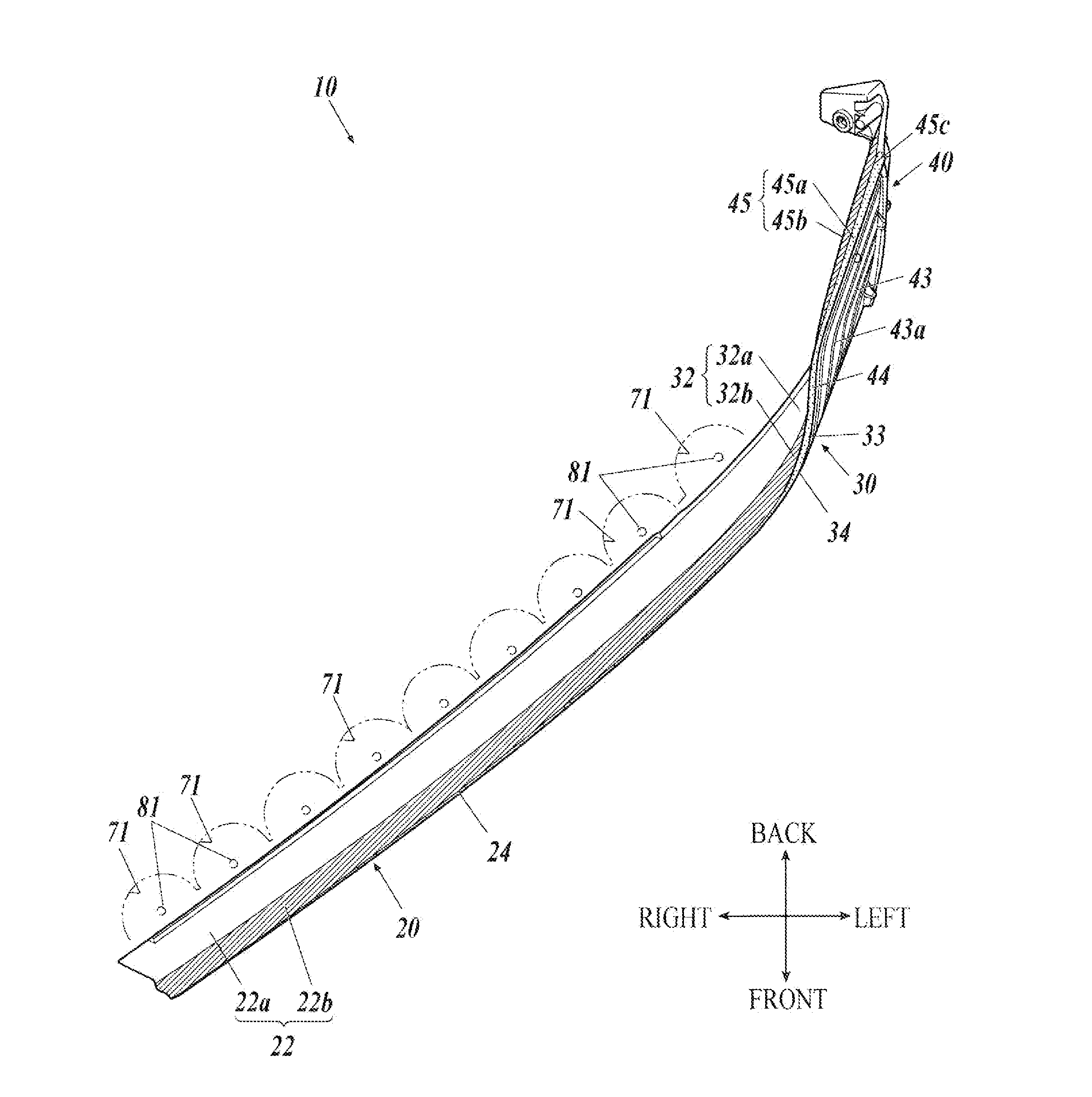
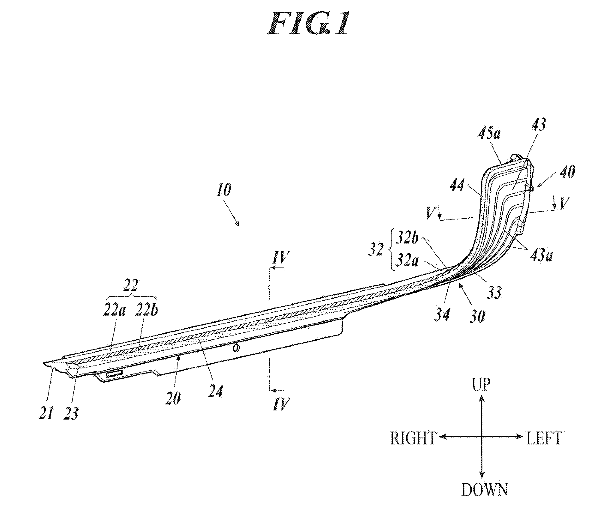
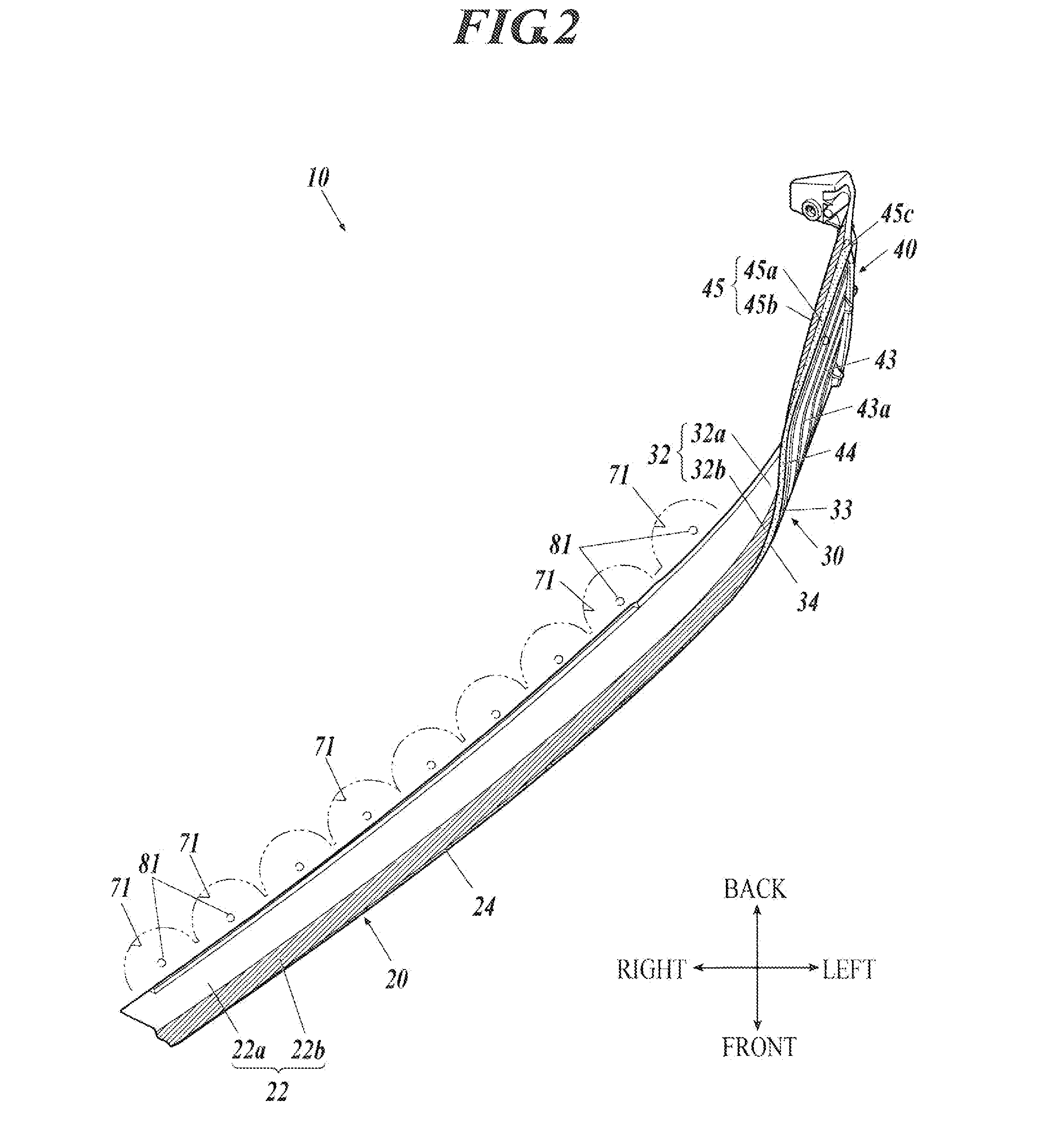
[0019]An illuminator 1 for a vehicle will now be described with reference to FIGS. 1 to 5. FIG. 1 is a front view of a light guiding body 10 for the illuminator 1. FIG. 2 is a top view of the light guiding body 10. FIG. 3 is a back view of the light guiding body 10. FIG. 4 is a cross-sectional view of the illuminator 1 showing a section along the line IV-IV of FIG. 1 viewed from the direction indicated by the arrows. FIG. 5 is a cross-sectional view of the illuminator 1 showing a section along the line V-V of FIG. 1 viewed from the direction indicated by the arrows. In the following description, “front”, “back”, “left”, “right”, “up”, and “down” refer...


PUM


Abstract

An illuminator includes a strip-shaped light guide and a plurality of light sources. The light sources are disposed along one end surface in the width direction of the light guide to allow light to be incident on the one end surface. The light guide guides the light of the light sources from the one end surface to the other end surface in the width direction of the light guide. The one end surface and the other end surface of the light guide are light-diffusing surfaces. The width of the light guide is larger than the thickness of the light guide.

Description

BACKGROUND OF THE INVENTION[0001]1. Field of the Invention[0002]The present invention relates to an illuminator and more particularly to a technique using a strip-shaped light guide.[0003]2. Description of Related Art[0004]Japanese Unexamined Patent Application Publication No. 2014-86202 discloses the following illuminator for a vehicle: multiple LEDs facing downward are arranged at some interval in the horizontal direction, multiple reflectors are disposed under the respective LEDs, the reflectors are arranged in the direction in which the LEDs are arranged, and a transparent strip-shaped front plate is disposed in front of the reflectors. The front plate, which is upright, extends in the horizontal direction. The thickness in the front-back direction of the front plate is smaller than the width in the up-down direction of the front plate. The front plate has a textured back surface. When the LEDs emit light and the front plate is seen from the front, the front plate looks luminous...

Claims


Application Information

Patent Timeline
Patent Type & Authority Applications(United States)
IPC IPC(8): F21V8/00F21W107/10
CPCG02B6/0043G02B6/0068G02B6/0046F21V19/00G02B6/0035G02B6/0038G02B6/0045F21S43/14F21S43/239F21S43/249F21S43/40
Inventor BAN, KAZUYASHIMIZU, KENTAROSAGAWA, MASAHIROOKU, KOTARO
Owner HONDA MOTOR CO LTD
Why Eureka
Try Eureka