Single section lift-up technique for eyelash extensions

Inactive Publication Date: 2016-04-07
NGUYEN QUYEN
View PDF14 Cites 15 Cited by
  • Summary
  • Abstract
  • Description
  • Claims
  • Application Information

AI Technical Summary

Benefits of technology

[0020]AN OBJECT of the present invention is to provide a single section lift-up

Problems solved by technology

Furthermore, even though these innovations may be suitable for the specific individual purposes to which they ad

Method used


Image

  • Single section lift-up technique for eyelash extensions
  • Single section lift-up technique for eyelash extensions
  • Single section lift-up technique for eyelash extensions

Examples


Example

REFERENCE NUMERALS UTILIZED IN THE DRAWING

[0041]110 eyelid[0042]112 gel pad[0043]114 surgical tape[0044]116 upper natural eyelash[0045]118 curved tweezers[0046]120 false eyelash

DETAILED DESCRIPTION OF THE PREFERRED EMBODIMENT

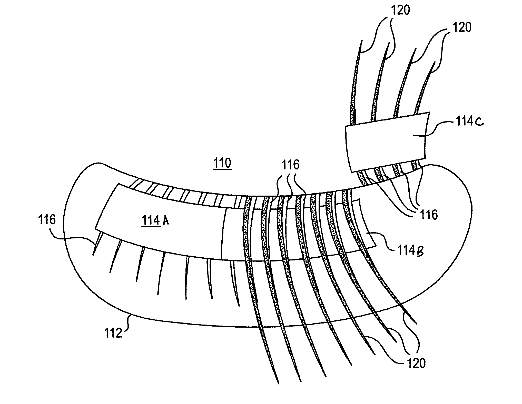
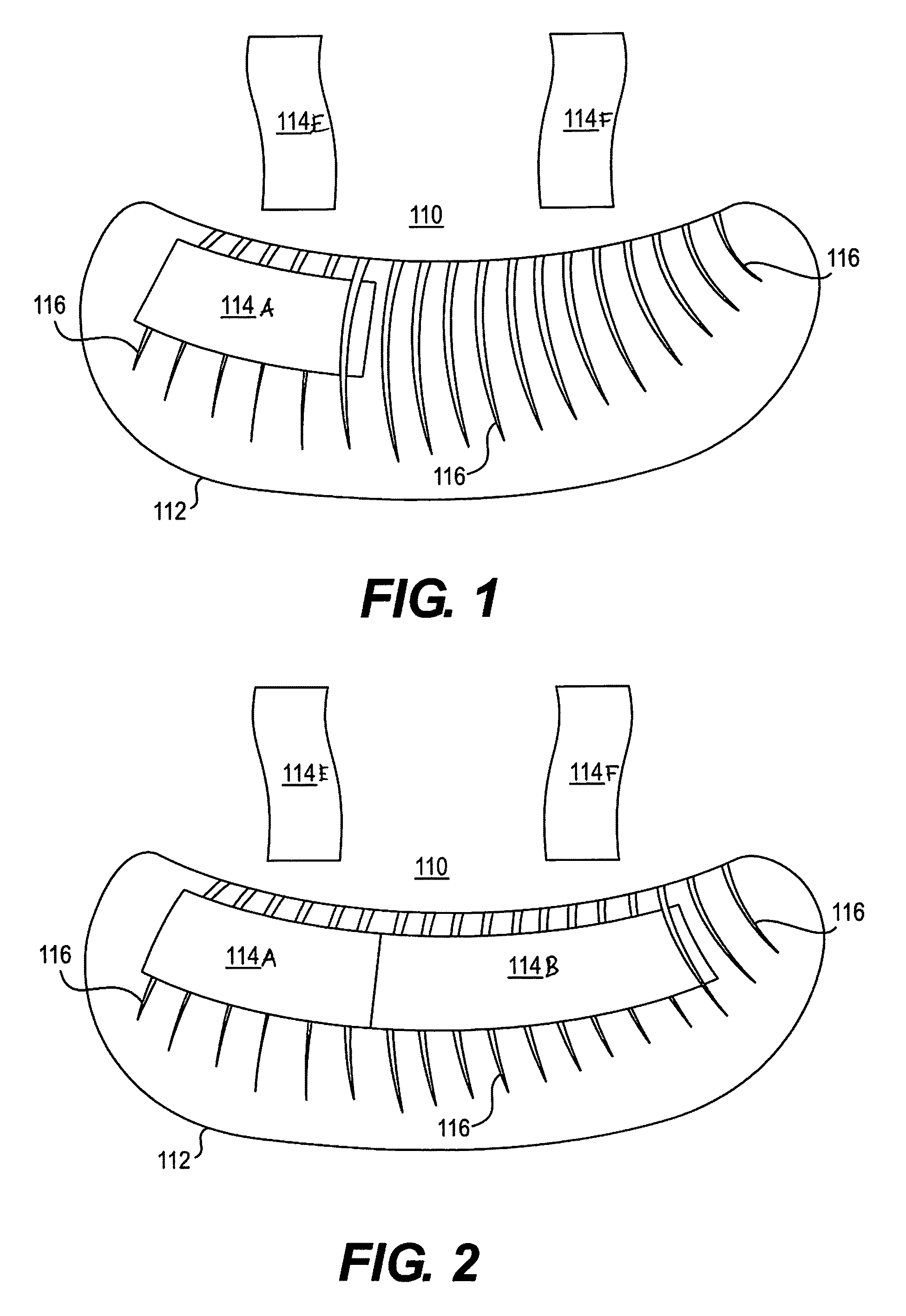
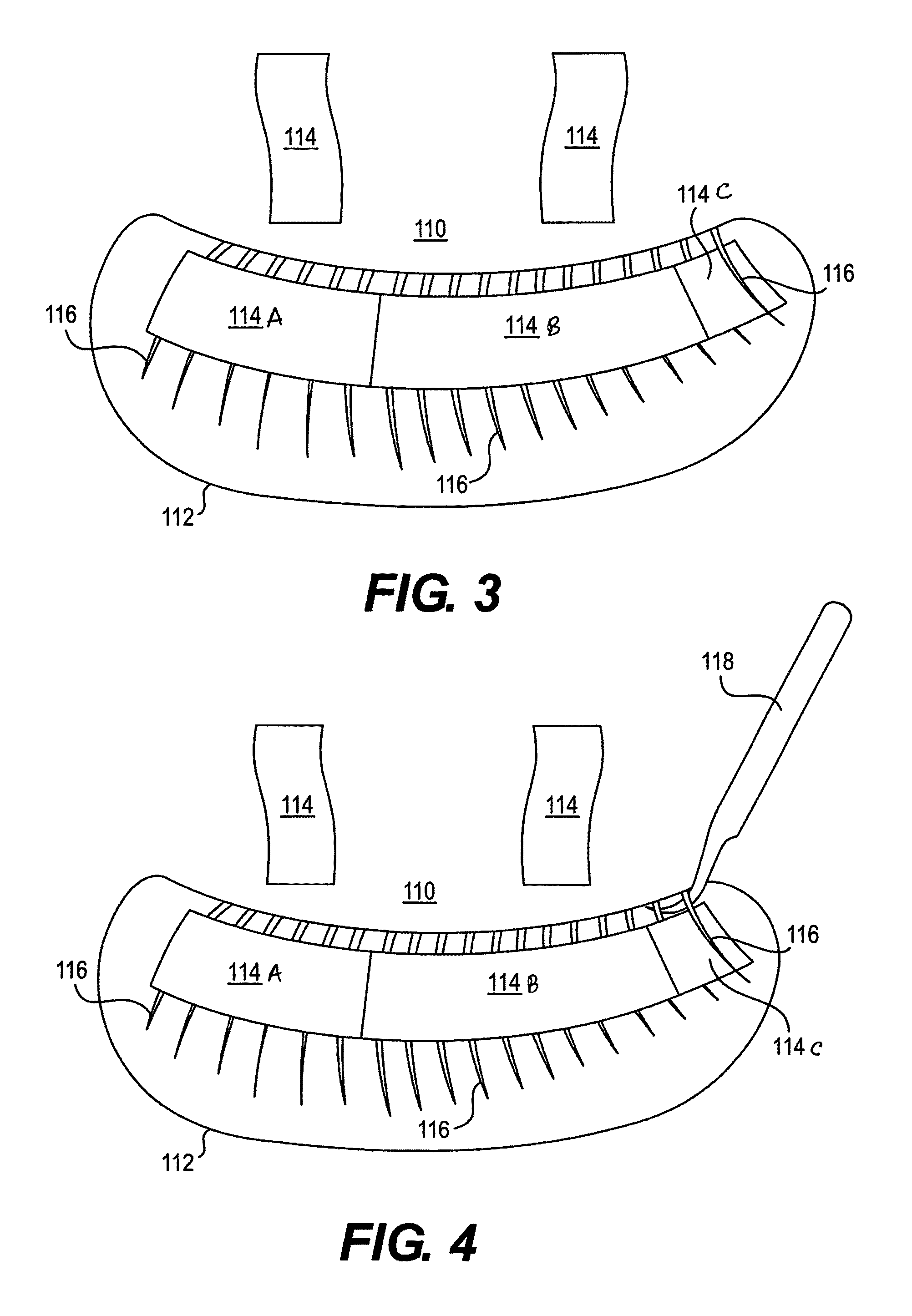
[0047]Before using the single section lift-up technique for eyelash extensions identify the eye shape of the client. By knowing the eye shape of the client it will help in choosing the look of the eyelash extensions. There is an open look being a short eyelash length in section one, a long eyelash length in section two, and a short eyelash length in section three. For an elongated look section one has a short eyelash length, section two long lash length, and section three a long eyelash length. Section one is called the inner section, section two is called the middle section (largest section), while section three is called the outer section.

[0048]Now choose the size for the client in which the individual false eyelash can range from 6 mm to 16 mm in length and 0...


PUM


Abstract

A single section lift-up technique for eyelash extensions with curved tweezers. Place three pieces of surgical tape over upper natural eyelashes to divide the eyelid into an outer corner, a middle and an inner corner section. Lift up the upper eyelashes one at a time from under the surgical tape on each section with a curved tweezers. Attach adhesive coated false eyelashes one at a time against the upper lashes of the each section with the curved tweezers. Attach adhesive coded false eyelashes one at a time against the upper eyelashes of each section with the curved tweezers.

Description

CROSS-REFERENCE TO RELATED APPLICATION[0001]This application claims the benefit of Provisional Patent Application No. 61 / 988,295, filed on May 4, 2014, in the United States Patent & Trademark Office, the disclosure of which is incorporated herein by reference.BACKGROUND OF THE INVENTION[0002]1. Field of the Invention[0003]The present invention relates to false eyelashes and more particularly, a single section lift-up technique for eyelash extensions.[0004]Individual eyelash extensions have been around for years. Many professional eyelash techs indicate that the individual single eyelash application takes a long time and is very straining to the eyes. Professionals have a hard time separating each individual natural eyelash and isolate it. Using two tweezers one in each hand is hard for some to do knowing that some people can't use both hands at the same time.[0005]Eyelash extensions are any number of enhancements designed to add length, thickness and fullness to natural eyelashes. T...

Claims


Application Information

Patent Timeline
IPC IPC(8): A41G5/02
CPCA41G5/02
Inventor NGUYEN, QUYEN T.
Owner NGUYEN QUYEN
Why Eureka
Try Eureka