Medical imaging system having microwave emission/reception

a medical imaging and microwave technology, applied in the field of medical imaging systems with microwave antennas, can solve the problems of system however raising a certain number of difficulties, liquid generally having many dielectric losses at preferred working frequencies, and posing difficulties in sealing, insulation of transmitter/sensor probes,

Active Publication Date: 2016-05-05
MVG IND +1
View PDF7 Cites 5 Cited by
  • Summary
  • Abstract
  • Description
  • Claims
  • Application Information

AI Technical Summary

Problems solved by technology

However, even if it is possible to modify the nature of the liquid to obtain the preferred dielectric permittivity such liquid generally has many dielectric losses at preferred working frequencies.
It also poses difficulties in terms of sealing, insulation of the transmitter/sensor probes with the medium under observation, hygiene, cleaning, conservation over time, variation in electromagnetic characteristics over time and as a function of temperature.
Such a system however raises a certain number of difficulties.
The emission/reception structure proposed in the article mentioned hereinabove is limited in terms of robustness of imagi

Method used


Image

  • Medical imaging system having microwave emission/reception
  • Medical imaging system having microwave emission/reception
  • Medical imaging system having microwave emission/reception

Examples


Embodiment Construction

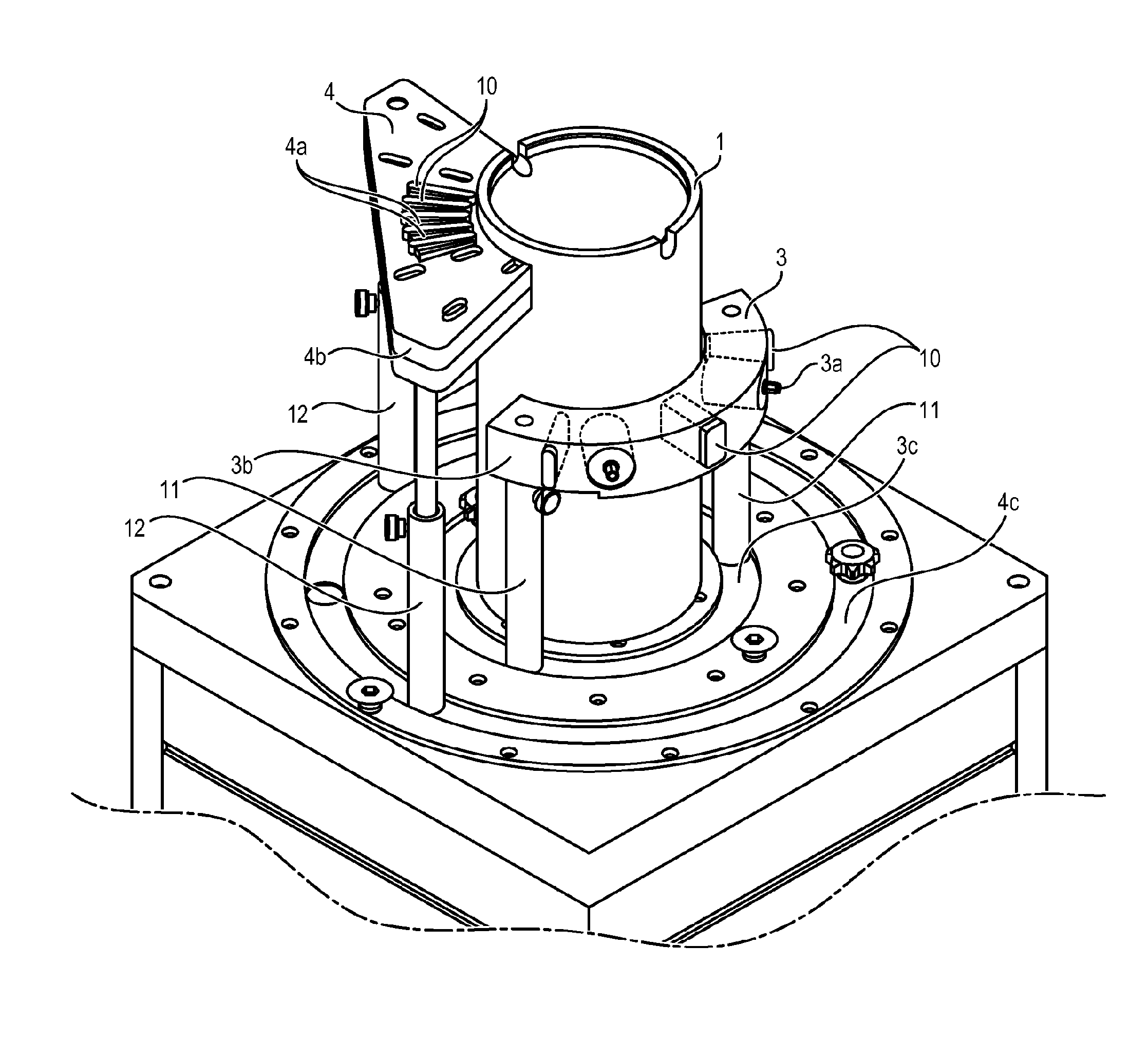
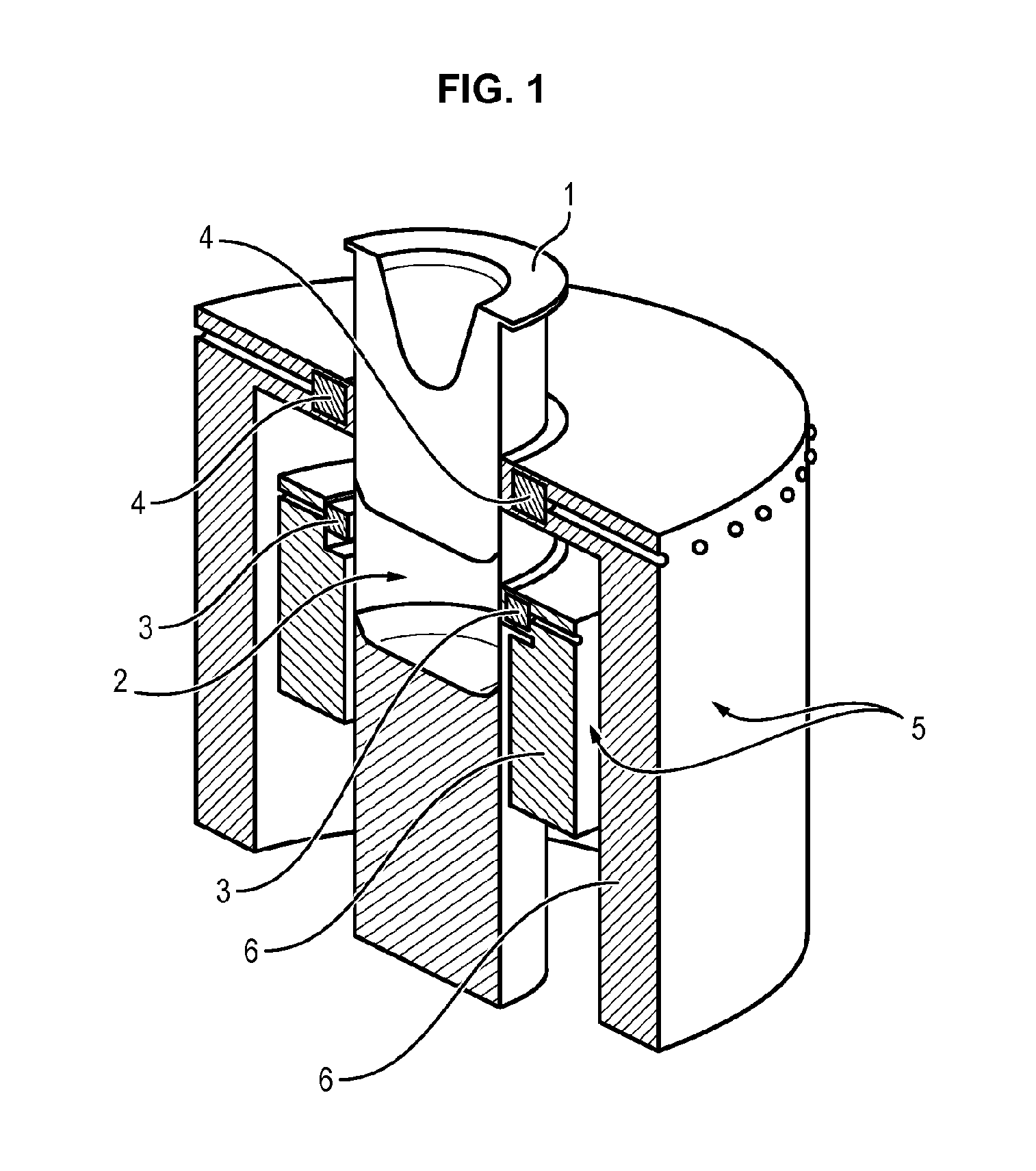
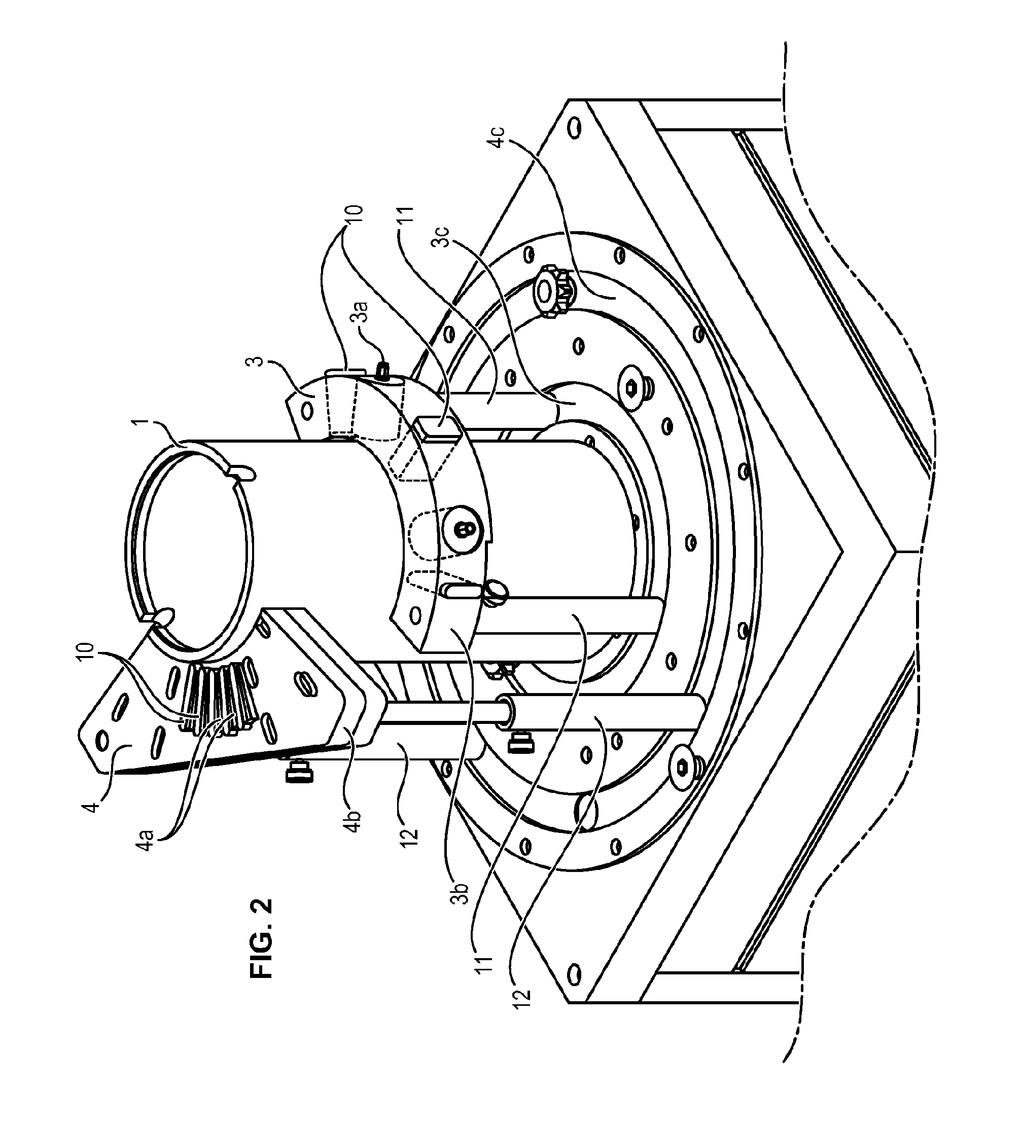
[0028]In the embodiment of FIG. 1, the device comprises a shell made of dielectric material 1 intended to receive the breast of the patient, a container 2 in which is placed this shell 1, at least one array 3 of transmission probes 3a, at least one array 4 of reception probes 4a, and a set of metallic casings 5 and electromagnetic absorbents 6 made of foam which enclose the container 2 and the arrays 3 and 4.

[0029]The shell 1 has an external form complementary to the internal form, cylindrical in this case, of the container 2 in which it is kept. Inside it has a hollow impression intended to receive the breast of a patient.

[0030]This shell 1 is detachable relative to the container 2. The device is connected to a set of shells 1. The external forms of the shells of the set of shells are identical. But the impressions are different and allow adaptation to the size of the breasts to be imaged.

[0031]The array 3 of transmission antennas 3a illuminates the medium under observation. In thi...


PUM


Abstract

The invention relates to a medical imaging system having microwave emitting antennas and antennas for receiving the electromagnetic field, which are arranged around a space for receiving a human tissue medium to be observed, and comprising: an array (3) of emitting antennas and an array (4) of receiving antennas, wherein said two arrays (3, 4) are independent, and motors capable of angularly rotating and of translating the emitting array (3) and/or the receiving array (4) relative to the space under observation, in order to enable the scanning thereof.

Description

GENERAL FIELD AND PRIOR ART[0001]The present invention relates to a medical imaging system with microwave antennas.[0002]More particularly, the invention relates to imaging systems of this type for analysis of human tissue or organs permeable to electromagnetic waves.[0003]It applies in particular and advantageously to imaging of the breast.[0004]In microwave imaging systems, the choice of transition material between the antennas and the medium under observation is important to ensure proper penetration of waves into this medium. The dielectric characteristics of the transition material must be selected as a function of the medium to be observed to obtain better results at the level of the images.[0005]Also, ideally this transition material must have the fewest dielectric losses possible to limit the absorption of energy of the electromagnetic wave.[0006]For this purpose it is ensured most often to immerse the antennas in a liquid with the biological tissues to be imaged. However, e...

Claims


Application Information

Patent Timeline
IPC IPC(8): A61B5/05A61B5/00
CPCA61B5/708A61B5/0507A61B5/4312G01S13/89A61B2562/0228A61B2562/143
Inventor CASTELLI, JUAN CARLOSDUCHESNE, LUCTESSIER, VIRGINIEDURAND, LUDOVICGARREAU, PHILIPPEADNET, NICOLASTHIEBAUT, STEPHANE
Owner MVG IND
Why Eureka
Try Eureka