Aircraft engine attachment device, and corresponding aircraft

a technology for aircraft engines and components, applied in the direction of aircraft power plants, power plant arrangements/mountings, power plant construction, etc., can solve the problems of affecting the maintenance operation of aircraft, the wear of engine attachment components is significant, and the wear of the shackle and/or the clevis mount is premature, so as to reduce the wear of engine attachment components and the effect of maintenance operations

Inactive Publication Date: 2016-05-05
AIRBUS OPERATIONS (SAS)
View PDF4 Cites 15 Cited by
  • Summary
  • Abstract
  • Description
  • Claims
  • Application Information

AI Technical Summary

Benefits of technology

[0011]More specifically, one objective of the invention is to provide an aircraft engine attachment device for which maintenance operations are reduced.
[0012]One particular objective of the invention is to provide such an aircraft engine attachment device in which the wearing of the engine attachment components is reduced.

Problems solved by technology

Such contact between components subjected to very substantial loadings and vibrations may cause premature wearing of the shackle and / or of the clevis mounts, potentially requiring them to be replaced at closely-spaced intervals.
This replacement of components of course represents a significant cost to the operators of the aircraft.

Method used


Image

  • Aircraft engine attachment device, and corresponding aircraft
  • Aircraft engine attachment device, and corresponding aircraft
  • Aircraft engine attachment device, and corresponding aircraft

Examples


Embodiment Construction

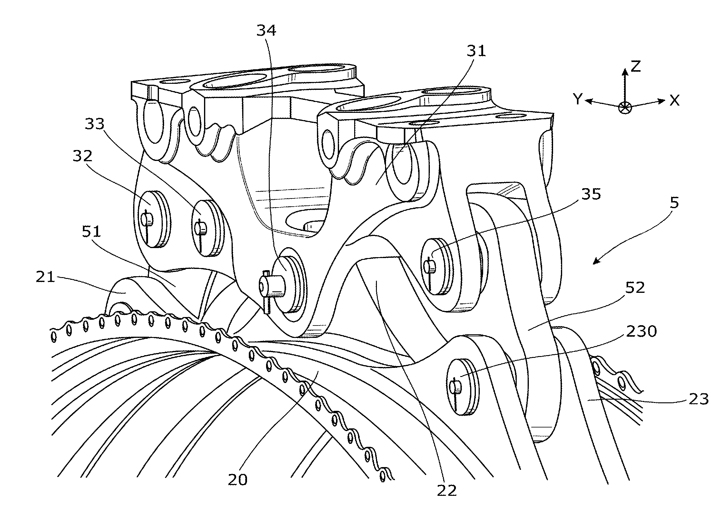
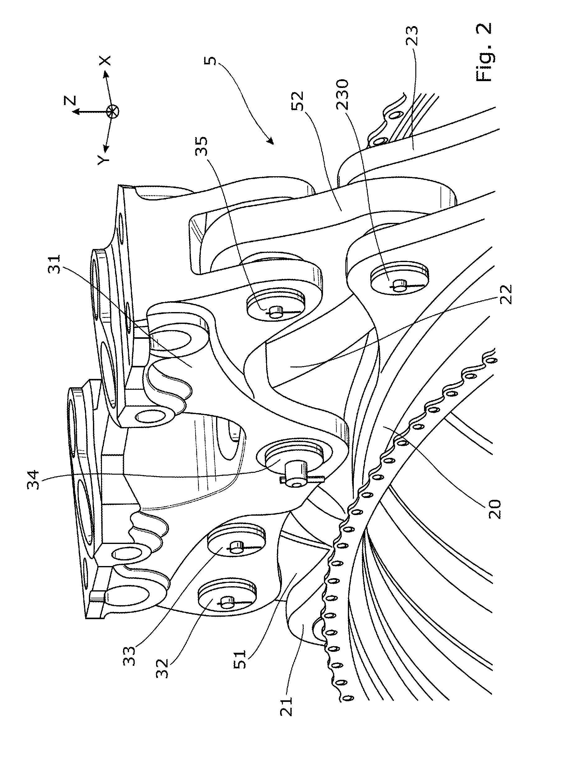
[0032]FIGS. 2 and 3 depict the rear suspension 5 of an aircraft engine 2. This suspension 5 comprises a beam 31 that can be secured to a pylon 3 of the aircraft. This beam 31 comprises a number of clevis mounts, a clevis mount in the present description being made up of two substantially parallel cheeks bearing at least one clevis pin extending from one cheek to the other. More specifically, the beam 31 comprises a clevis mount 32 bearing the clevis pins 320 and 330, which are oriented in the longitudinal direction, a clevis mount 34 bearing a clevis pin 340 oriented in the longitudinal direction, and a clevis mount 35, also referred to in the present description as the “first clevis mount,” which bears a clevis pin 350 oriented in the longitudinal direction.

[0033]The pin 350, borne by the first clevis mount 35, is connected to a pin 230, borne by a clevis mount 23 secured to the casing 20 of the engine 2. This clevis mount 23 is also referred to in the present description as the “s...


PUM


Abstract

A device for attaching an aircraft engine to a pylon secured to the aircraft, the attachment device comprising a beam secured to the pylon and a first clevis mount comprising two cheeks connected to one another by a first clevis pin. A second clevis mount is secured to the engine and comprises two cheeks connected to one another by a second clevis pin. A shackle is rotatably connected to the first and second pins by first and second spherical joints. The attachment device further comprises at least one pair of washers positioned around one of the pins, one washer on each side of the shackle, and separating the shackle from the cheeks of the clevis mount bearing the one of the pins. The shackle, in its extreme positions of rotation about the one of the pins passing through the two spherical joints, coming into contact with the washers.

Description

CROSS-REFERENCES TO RELATED APPLICATIONS[0001]This application claims the benefit of the French patent application No. 1460416 filed on Oct. 30, 2014, the entire disclosures of which are incorporated herein by way of reference.FIELD OF THE INVENTION[0002]The present invention relates to an aircraft engine attachment device. It also relates to an aircraft comprising such an attachment device.BACKGROUND OF THE INVENTION[0003]In many aircraft intended for carrying passengers, the aircraft engines are suspended from a pylon which is itself fixed to the underside of the aircraft wing structure.[0004]FIG. 1 schematically depicts a connection between a wing 1 of an aircraft and an engine 2, consisting of a bypass turbojet engine. This connection is afforded by means of the pylon 3 which allows the loads generated by the engine 2 to be transmitted to the structure of the aircraft and also allows fuel pipes, electrical, hydraulic and air systems to be run between the engine 2 and the wing 1 ...

Claims


Application Information

Patent Timeline
Patent Type & Authority Applications(United States)
IPC IPC(8): B64D27/26
CPCB64D2027/262B64D27/26B64D2027/264B64D2027/266
Inventor SERRA, BRUNOGARRIGUES, RICHARD
Owner AIRBUS OPERATIONS (SAS)
Why Eureka
Try Eureka