Stereoscopic helmet display

Active Publication Date: 2016-05-05
ILLINOIS TOOL WORKS INC
View PDF8 Cites 75 Cited by
  • Summary
  • Abstract
  • Description
  • Claims
  • Application Information

AI Technical Summary

Problems solved by technology

However, these power supplies may often be remote from a work area, thereby causing delays if a user changes settings of a power supply due to travel to and from the power supply to make the changes.

Method used


Image

  • Stereoscopic helmet display
  • Stereoscopic helmet display
  • Stereoscopic helmet display

Examples


Embodiment Construction

[0014]As will be described in detail below, provided herein are systems and methods for viewing and controlling power sources remotely. By viewing and controlling the power sources remotely, an operator may weld a workpiece with desired parameters without walking away from the workpiece. In other embodiments, a welding operator may control the parameters of a weld without spending valuable weld time traveling to the power supply to view and control the power supply. Thus, the operator may weld more quickly and efficiently with desired parameters. Furthermore, the operator may confirm welding parameters prior to a weld without substantial delay that may be required when having to walk back to the power source to change welding parameters.

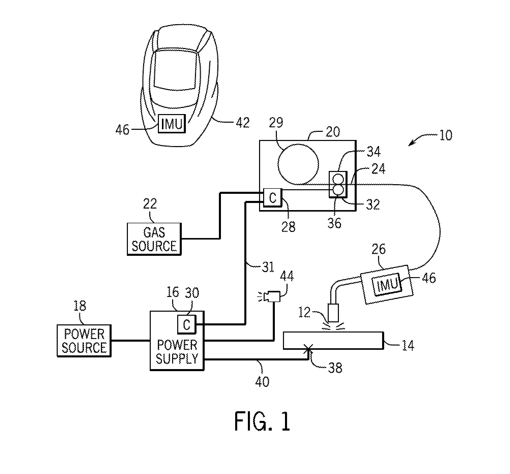
[0015]Turning now to the figures, FIG. 1 is a block diagram of an embodiment of a welding system 10 in accordance with the present techniques. The welding system 10 is designed to produce a welding arc 12 with a workpiece 14 (e.g., pipe). The welding...


PUM

PropertyMeasurementUnit
poweraaaaaaaaaa
currentaaaaaaaaaa
voltageaaaaaaaaaa

Abstract

A welding-type system includes a helmet having a first image capture device configured to capture a first set of images of a work area from a first perspective and a second image capture device configured to capture a second set of images of the work area from a second perspective. The helmet also includes an electronic display configured to display the first and second sets of images substantially simultaneously to cause a stereoscopic appearance of the work area via the electronic display. Moreover, the helmet includes an audible command translation unit configured to receive audible commands configured to adjust operation of a power supply configured to supply power for the welding-type system. Furthermore, the welding-type system includes a processing system communicatively coupled to the audible command translation unit and configured to adjust at least one parameter of the power supply based at least in part on the received audible commands.

Description

BACKGROUND[0001]The invention relates generally to welding systems and, more particularly, to sensing systems for displaying and changing power supply settings remotely.[0002]Welding is a process that has become ubiquitous in various industries for a variety of types of applications. For example, welding is often performed in applications such as shipbuilding, aircraft repair, construction, and so forth. The welding systems often include power supplies that may generate power for consumption during the welding process. However, these power supplies may often be remote from a work area, thereby causing delays if a user changes settings of a power supply due to travel to and from the power supply to make the changes.BRIEF DESCRIPTION[0003]In a first embodiment, a welding-type system includes a helmet having a first image capture device configured to capture a first set of images of a work area from a first perspective and a second image capture device configured to capture a second se...

Claims


Application Information

Patent Timeline
Patent Type & Authority Applications(United States)
IPC IPC(8): G06T19/00A61F9/06H04N5/247H04N5/232H04N13/04G06T7/00G06T7/20B23K9/095G06F3/01G02B27/01A42B3/04G06F3/16
CPCG06T19/006G06T2200/04A42B3/0433A61F9/06H04N5/247H04N5/23241G06F3/167G06T7/0004G06T7/2093B23K9/0956G06F3/012G02B27/017H04N13/0497H04N13/0486H04N13/0429G06T2207/30108A42B3/042B23K9/173B23K9/322G05B19/409G05B2219/35487G05B2219/45135H04N23/65H04N23/633G06T7/292H04N13/332H04N13/315H04N13/398H04N23/90
Inventor DENIS, MARC LEE
Owner ILLINOIS TOOL WORKS INC
Why Eureka
Try Eureka