
3D image display device

Active Publication Date: 2016-05-05
INNOLUX CORP
View PDF0 Cites 5 Cited by
  • Summary
  • Abstract
  • Description
  • Claims
  • Application Information

AI Technical Summary

Benefits of technology

The invention provides a 3D image display device that allows both resolution and clarity of image content to be maintained while presenting a 3D image to the observer. The device utilizes a light modulating unit to change the light path and generate image data at different positions on the pupil, resulting in a more immersive viewing experience. This is achieved without the need to divide the image data into smaller parts, reducing resolution loss and improving the overall clarity of the 3D image.

Problems solved by technology

However, the observer usually needs to wear a pair of 3D eyeglasses to watch the display of 3D image.
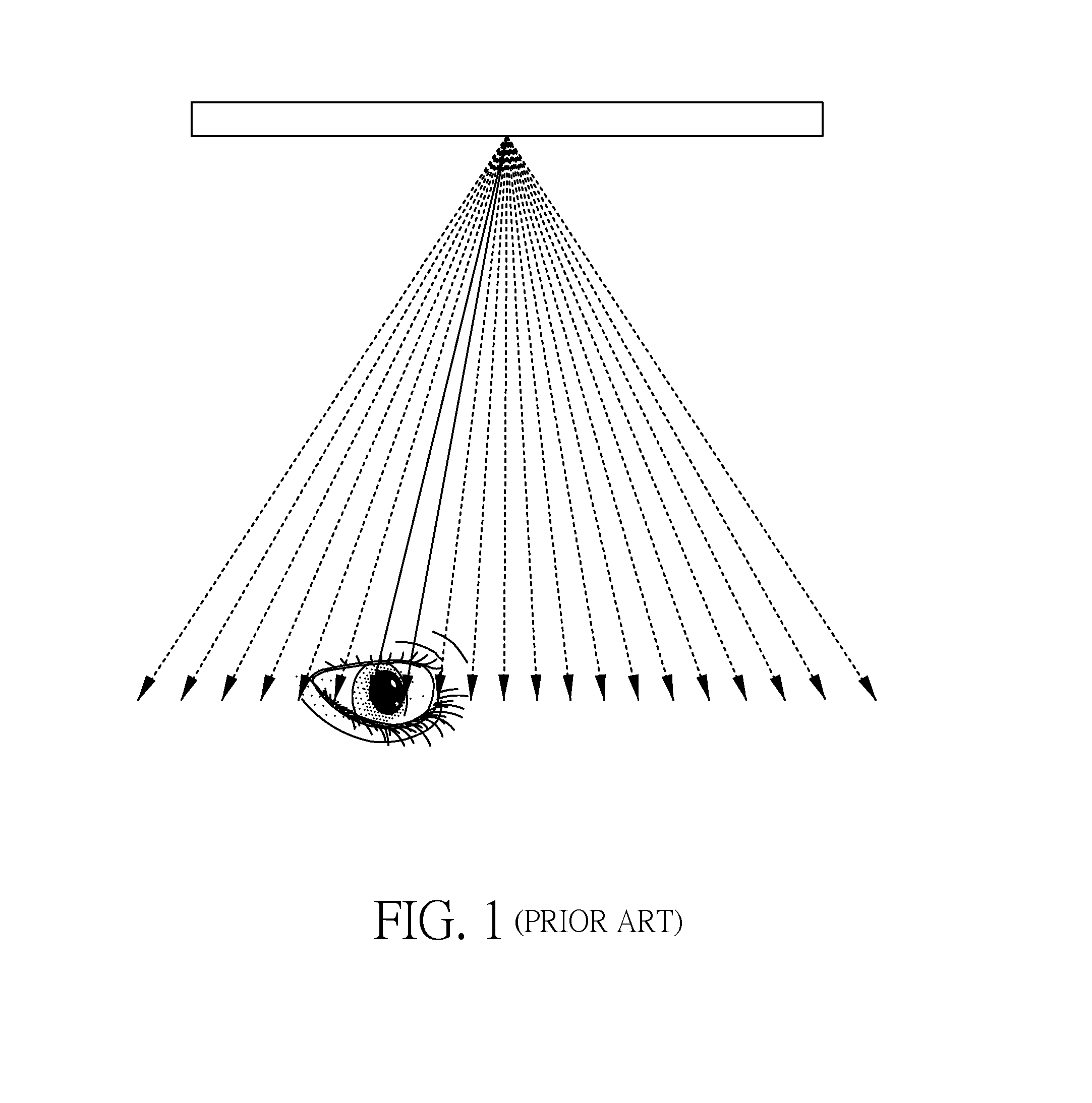
Even though autostereoscopy technique provided for allowing observers to view 3D image without wearing 3D eyeglasses has been applied to the display device, autostereoscopy technique is not satisfactory in depth of field and accommodation to human eyes.
It results in a great amount of resolution loss.

Method used


Image

  • 3D image display device
  • 3D image display device
  • 3D image display device

Examples


first embodiment

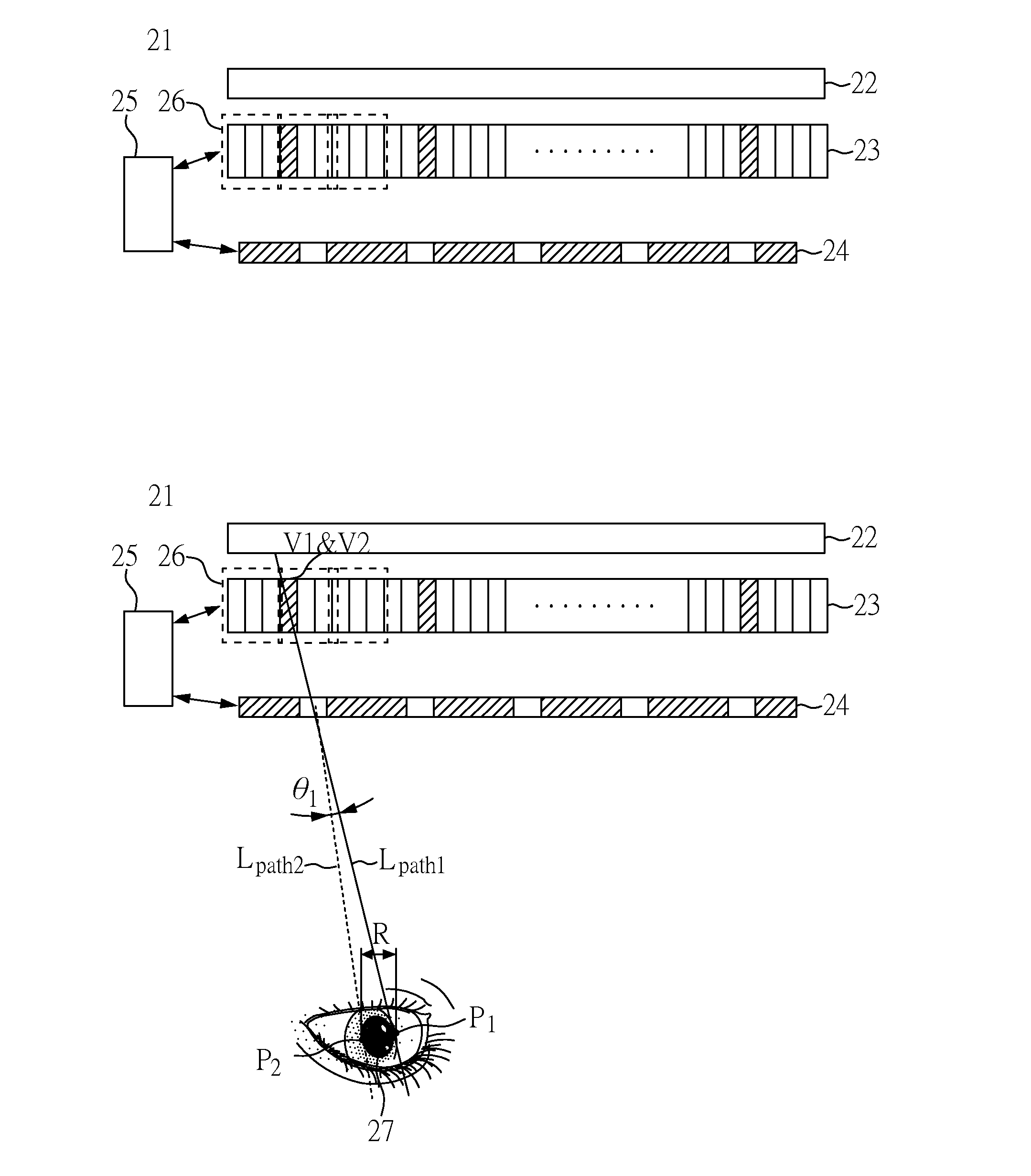
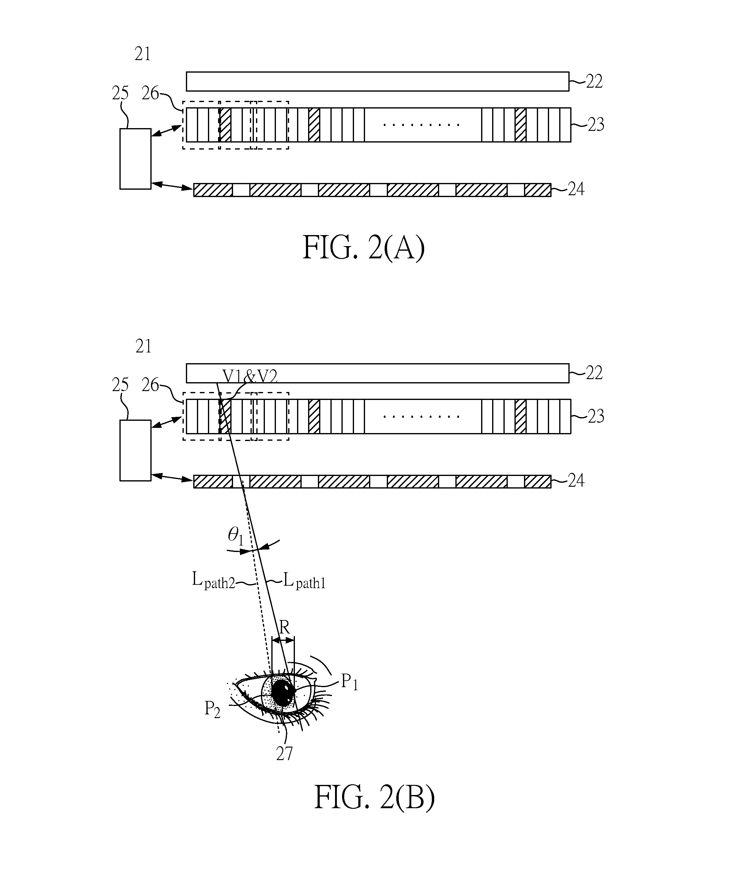
[0022]Please refer to FIG. 2(A). FIG. 2(A) schematically illustrates the structure of a 3D image display device 21 according to the invention. As shown in FIG. 2(A), the 3D image display device 21 includes a backlight unit 22, a display panel 23, a light modulating unit 24, and a controller 25. The backlight unit 22 is used to generate an original light. The display panel 23 has a plurality of pixels 26 that are respectively used to generate an image data, and each of the pixels are composed of at least three of sub-pixels, wherein total image data can form the image. The light modulating unit 24 is used to change the path of the original light. The controller 25 is electrically connected to the display panel 23 and the light modulating unit 24 for providing a control signal to control the display panel 23 and the light modulating unit 24. When the 3D image display device 21 is operated, the controller 25 provides a first signal to the display panel 23 and the light modulating unit ...

second embodiment

[0049]FIG. 6(A) schematically illustrates the structure of the 3D image display device 61 according to the invention. The 3D image display device 61 includes a backlight unit 62, a display panel 63, a light modulating unit 64, and a controller 65. The light modulating unit 64 may be a switchable barrier, a LC GRIN lens, a real lens, a fixed barrier or a switchable LC barrier. In this embodiment, the light modulating unit 64 is switchable barrier. The backlight unit 62 is used to generate an original light, and provide back light to the image. The display panel 63 has a plurality of pixels for generating an image and is deposited between the backlight unit 62 and the light modulating unit 64. The light modulating unit 64 has a plurality of barrier regions. The controller 65 is connected to the display panel 63 for providing a first signal to control the display panel 63 in the first time, and for providing a second signal to the display panel in a second time. When the 3D image displ...


PUM


Abstract

A 3D image display device includes a backlight unit for generating an original light, a display panel, a light modulating unit, and a controller connected to the display panel and the light modulating unit. According to a first signal, the original light passes through the display panel generates a first light, the first light passes through the light modulating unit, and has a first position on an objective plane parallel to the display panel. According to a second signal, the original light passes through the display panel to generate a second light, the second light passes through the light modulating unit and has a second position on the objective plane, wherein the first position is different from the second position.

Description

BACKGROUND OF THE INVENTION[0001]1. Field of the Invention[0002]The present invention relates to an image display device and, more particularly, to a 3D image display device.[0003]2. Description of Related Art[0004]Currently, the display of 3D image in the 3D image display device is achieved by using technologies to form binocular disparity of eyes of an observer. However, the observer usually needs to wear a pair of 3D eyeglasses to watch the display of 3D image. Even though autostereoscopy technique provided for allowing observers to view 3D image without wearing 3D eyeglasses has been applied to the display device, autostereoscopy technique is not satisfactory in depth of field and accommodation to human eyes. Hence, it still needs to use two eyes of the observer for 3D image formation.[0005]FIG. 1 is a system known as a super multi view (SMV) system for providing the 3D image that can be seen by the observer with single eye. The system divides an image data into 72 to 128 light ...

Claims


Application Information

Patent Timeline
IPC IPC(8): G09G3/34G09G3/36G09G3/20
CPCG09G3/3406G09G3/2074G09G2340/04G09G2320/0646G09G2320/068G09G3/36H04N13/31G02F1/134309G02B30/27G09G3/003G09G2300/023G02F1/29G02B30/24
Inventor SUMI, NAOKI
Owner INNOLUX CORP
Learn More