Intelligent Electrical Switch

a multi-way, intelligent technology, applied in the integration of power network operation systems, relays, data switching networks, etc., can solve the problems of system failure to operate in conjunction with existing wiring and hardwar

Active Publication Date: 2016-05-05
IVANI
View PDF14 Cites 61 Cited by
  • Summary
  • Abstract
  • Description
  • Claims
  • Application Information

AI Technical Summary

Benefits of technology

[0014]Because of these and other problems in the art, described herein, among other things, is an intelligent switching apparatus (301) which actuates a conventional mechanical switch (303) to cause a change in system state. Such a device does not merely mimic the behavior of a conventional system, but actually uses such a system, meaning that if the intelligent switching apparatus were inoperable for any reason, manual use of the switch would continue to function to cause a change in the system state (e.g., power a circuit on or off). Such a system has further advantages in that only one switch is replaced with the intelligent switch to allow the entire multi-way circuit to be toggled remotely. Further, such a smart switch can intelligently track system state knowledge and make decisions accordingly, rather than serving merely as a toggle.

Problems solved by technology

This essentially means that if an electrical path already exists in the system, operating a four-way switch will break the circuit.
However, these systems do not operate in conjunction with existing wiring and hardware.
This can add expense, hassle, and waste, as the existing equipment is lost.
This can be a problem in buildings with antique or non-standard fixtures, where replacement smart fixtures may not be available.
If communication is disrupted, the system no longer operates.
This makes such systems susceptible to catastrophic failure in the very circumstances where the fixture is likely to be needed.
Without a conventional wiring system as a fail-safe, these systems are unsuitable for use in many applications.
Thus, users who wish to add automation features to a residence or other building are forced to replace major components of the system and lose the security and / or reliability of conventional switching technologies.

Method used


Image

  • Intelligent Electrical Switch
  • Intelligent Electrical Switch
  • Intelligent Electrical Switch

Examples


Embodiment Construction

)

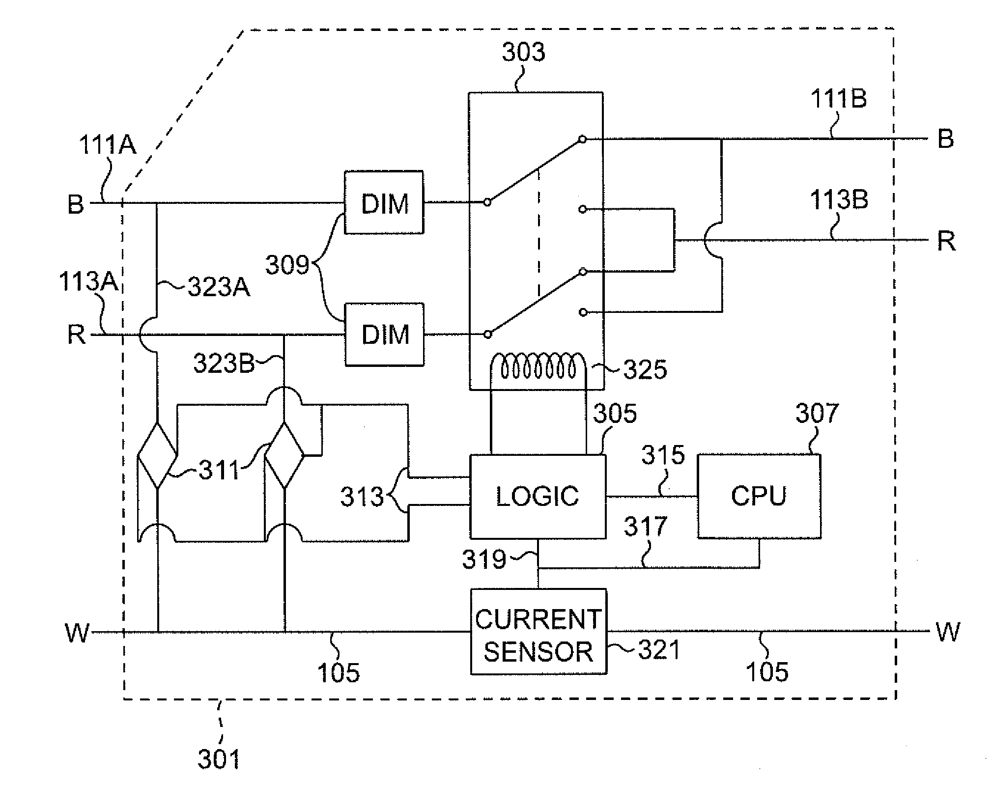
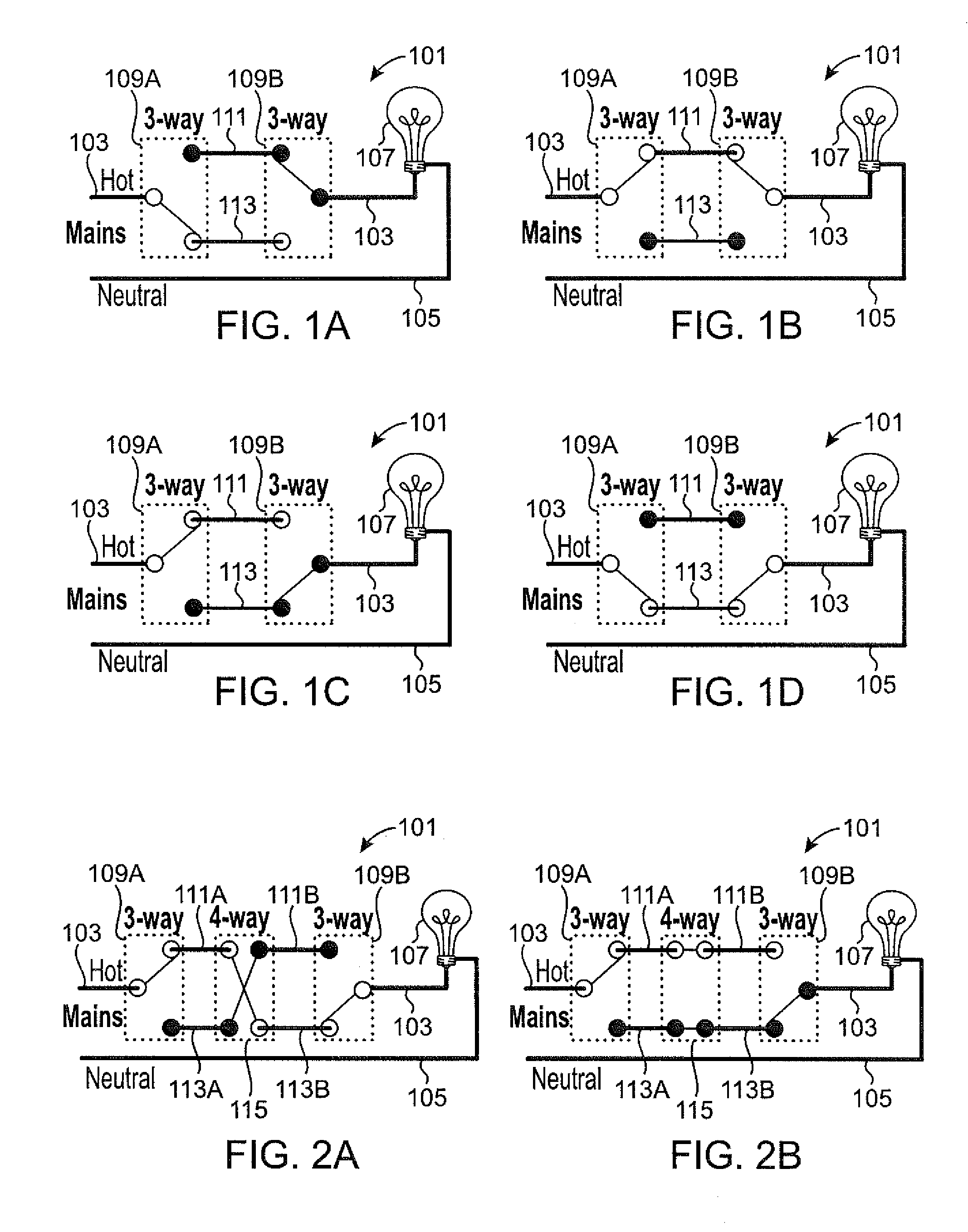
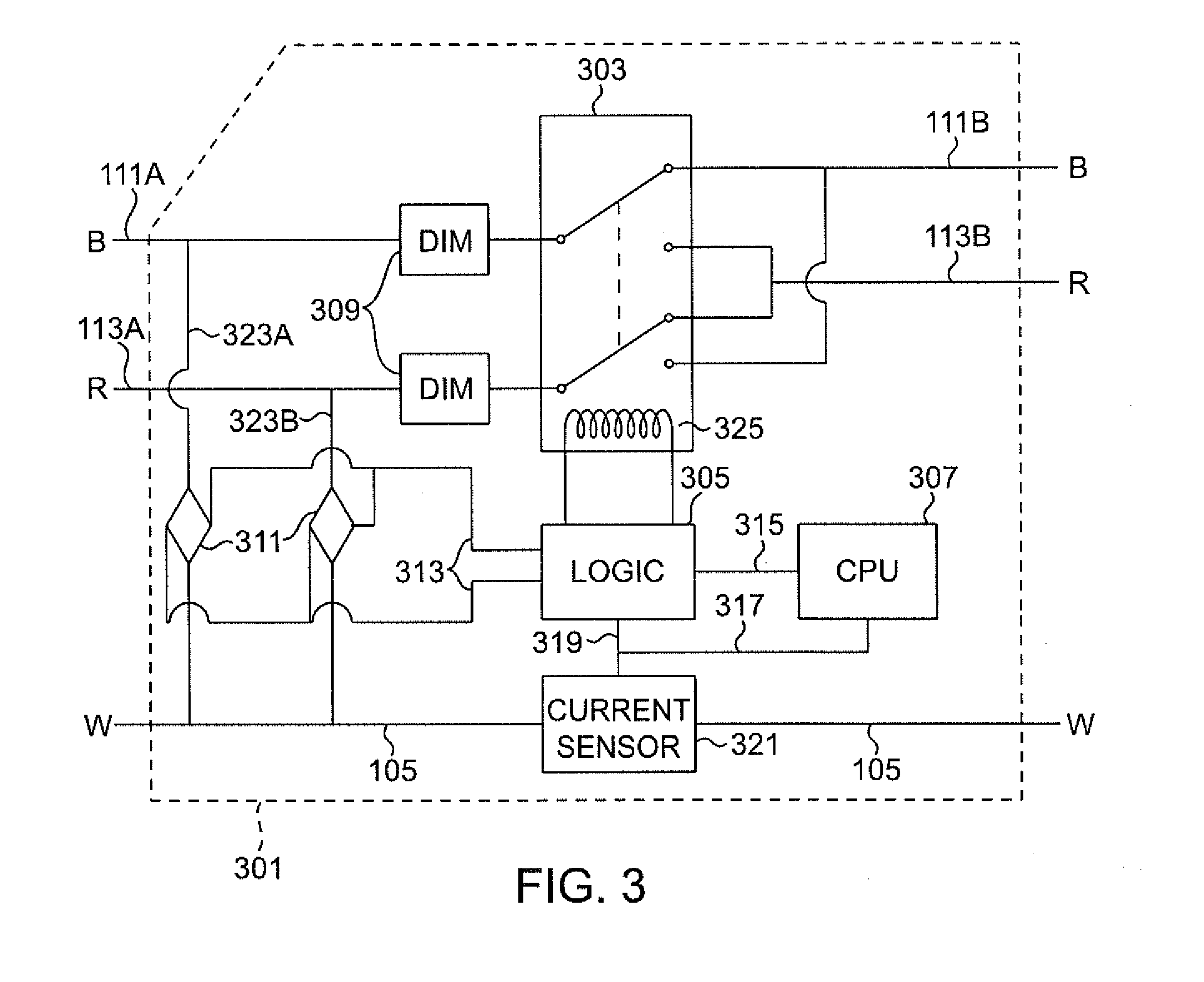
[0019]The following detailed description and disclosure illustrates by way of example and not by way of limitation. This description will clearly enable one skilled in the art to make and use the disclosed systems and methods, and describes several embodiments, adaptations, variations, alternatives and uses of the disclosed systems and methods. As various changes could be made in the above constructions without departing from the scope of the disclosures, it is intended that all matter contained in the description or shown in the accompanying drawings shall be interpreted as illustrative and not in a limiting sense.

[0020]Throughout this disclosure, the term “computer” describes hardware which generally implements functionality provided by digital computing technology, particularly computing functionality associated with microprocessors. The term “computer” is not intended to be limited to any specific type of computing device, but it is intended to be inclusive of all computational...


PUM


Abstract

An intelligent electrical switch comprising a conventional mechanical switch connected to a computer system in communication with an external device and receiving instructions therefrom. The switch may be installed in an existing circuit to replace one switch in a multi-way wiring geometry, and includes a sensor detecting current on the neutral line. By determining the circuit state, the switch can determine whether, when instructions are received wirelessly to power the circuit on or off, the mechanical switch element should be toggled.

Description

CROSS REFERENCE TO RELATED APPLICATIONS[0001]This application is a Continuation-in-Part of U.S. Utility Application No. 14 / 698,690, filed Apr. 28, 2015, which in turn claims benefit of U.S. Provisional Application No. 62 / 074,902, filed Nov. 4, 2014. This application also claims benefit of U.S. Provisional Application No. 62 / 074,902, filed Nov. 4, 2014. The entirety of both of these applications is incorporated herein by reference.BACKGROUND[0002]1. Field of the Invention[0003]This disclosure is related to the field of electrical wiring, and more particularly to systems, methods, and apparatus pertaining to an intelligent multi-way electric switch.[0004]Electrical systems commonly include manual switching systems comprising a switch element combined into a three-way or four-way wiring geometry to provide users with the ability to operate a circuit from multiple locations. For example, it is desirable, and often required by building code, to have a light switch at each entrance to a r...

Claims


Application Information

Patent Timeline
Patent Type & Authority Applications(United States)
IPC IPC(8): H01H9/54
CPCH01H9/54H04L12/2816H04L2012/2841H05B47/19H05B39/02H01H2300/03Y04S20/246Y04S40/126H05B47/175H02J2310/12H02J13/00024H02J13/00026H02J13/00004H02J13/00036Y02B70/30Y04S20/14Y02B20/40Y02B90/20Y04S20/20H02J13/00
Inventor WOOTTON, MATTHEWWOOTTON, JOHNNISSMAN, CHRISMCKINNEY, JUSTIN
Owner IVANI
Why Eureka
Try Eureka