Linear motor with reduced cogging force
- Summary
- Abstract
- Description
- Claims
- Application Information
AI Technical Summary
Benefits of technology
Problems solved by technology
Method used
Image
Examples
Embodiment Construction
[0037]Referring to the accompanying drawings, embodiments of the present invention will be described. The constituent elements shown in the drawings are depicted in different scales as necessary for better understanding of the present invention. Further, the same or corresponding constituents are allotted with the same reference numerals.
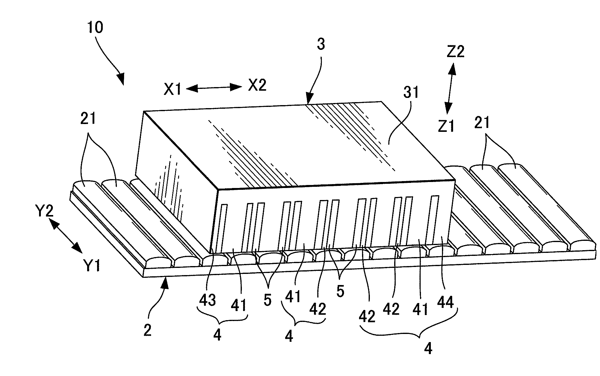
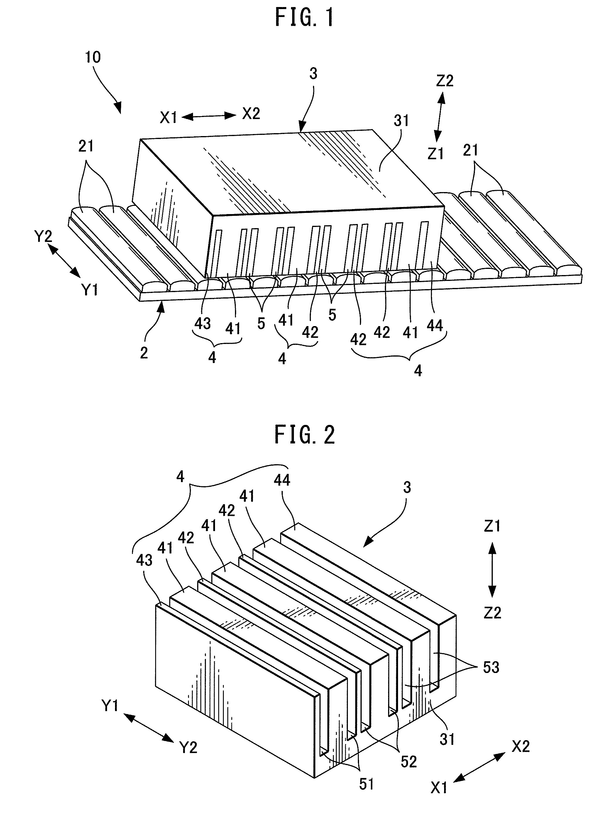
[0038]FIG. 1 is a perspective view showing a linear motor according to one embodiment. A linear motor 10 includes a magnet board 2 extending in the moving directions of the linear motor 10, indicated by arrows X1 and X2, and an armature 3 provided opposite to the magnet board 2. On a surface of the magnet board 2 facing the armature 3, elongated magnets 21 extending in directions (the directions indicated by arrows Y1 and Y2) perpendicular to the moving direction of the linear motor 10 are arranged at equal intervals. The magnets 21 are fixed to the magnet board 2 by known means such as screw fitting, adhesives, additional locking parts, or the like...
PUM
 Abstract
Description
Claims
Application Information
 - R&D
- Intellectual Property
- Life Sciences
- Materials
- Tech Scout
- Unparalleled Data Quality
- Higher Quality Content
- 60% Fewer Hallucinations
Browse by: Latest US Patents, China's latest patents, Technical Efficacy Thesaurus, Application Domain, Technology Topic, Popular Technical Reports.
© 2025 PatSnap. All rights reserved.Legal|Privacy policy|Modern Slavery Act Transparency Statement|Sitemap|About US| Contact US: help@patsnap.com


