Tool Cabinet

Inactive Publication Date: 2016-05-12
CHANG TING YU
View PDF6 Cites 18 Cited by
  • Summary
  • Abstract
  • Description
  • Claims
  • Application Information

AI Technical Summary

Benefits of technology

[0008]According to the present invention, a tool cabinet includes a cabinet body having a bottom side, a top side, and a lateral side. The bottom and top sides are disposed oppositely in a height direction of the cabinet body. The lateral side extends in the height direction of the cabinet body from the bottom side to the top side. The bottom, top, and the lateral sides cooperate to define a chamber with an opening. At least one pair of slide modules is disposed oppositely on the lateral side. At least one drawer is received by the chamber and slidably engaged with and retained by the at least one pair of slide modules between an open position partially extending outside chamber through the opening and a closed position received in the chamber. At least one opening and closing device is engaged with the cabinet body and the at least one drawer and is configured to selectively prevent the at least one drawer from being opened. The at least one drawer is moved from the closed position to the open position in a first direction upon being opened. The opening and closing device includes a first and second holder, a displacing member, a flipping member, a biasing member, and a control input. The first and second holders are attached to a front panel of a drawer box of the at least one drawer. The

Problems solved by technology

However, the core technology of such conventional structure resides on the position of installing the pivot 52 onto the pivot member 51, and the choice of such position faces several difficulties.
On the contrary,

Method used


Image

  • Tool Cabinet
  • Tool Cabinet
  • Tool Cabinet

Examples


Embodiment Construction

[0020]The present invention will become clearer in light of the following detailed description of an illustrative embodiment of this invention described in connection with the drawings. It is intended that the embodiments and drawings disclosed herein are to be considered illustrative rather than restrictive.

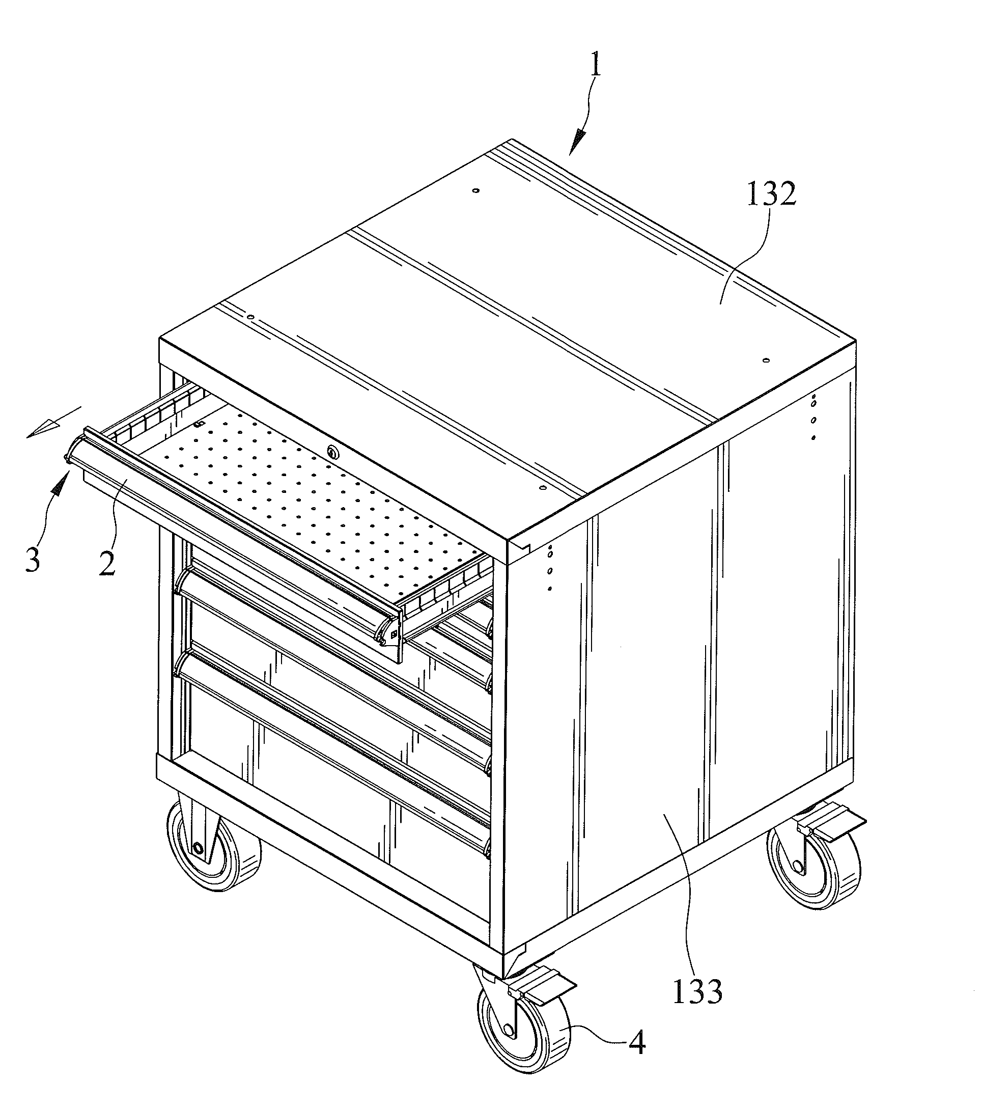
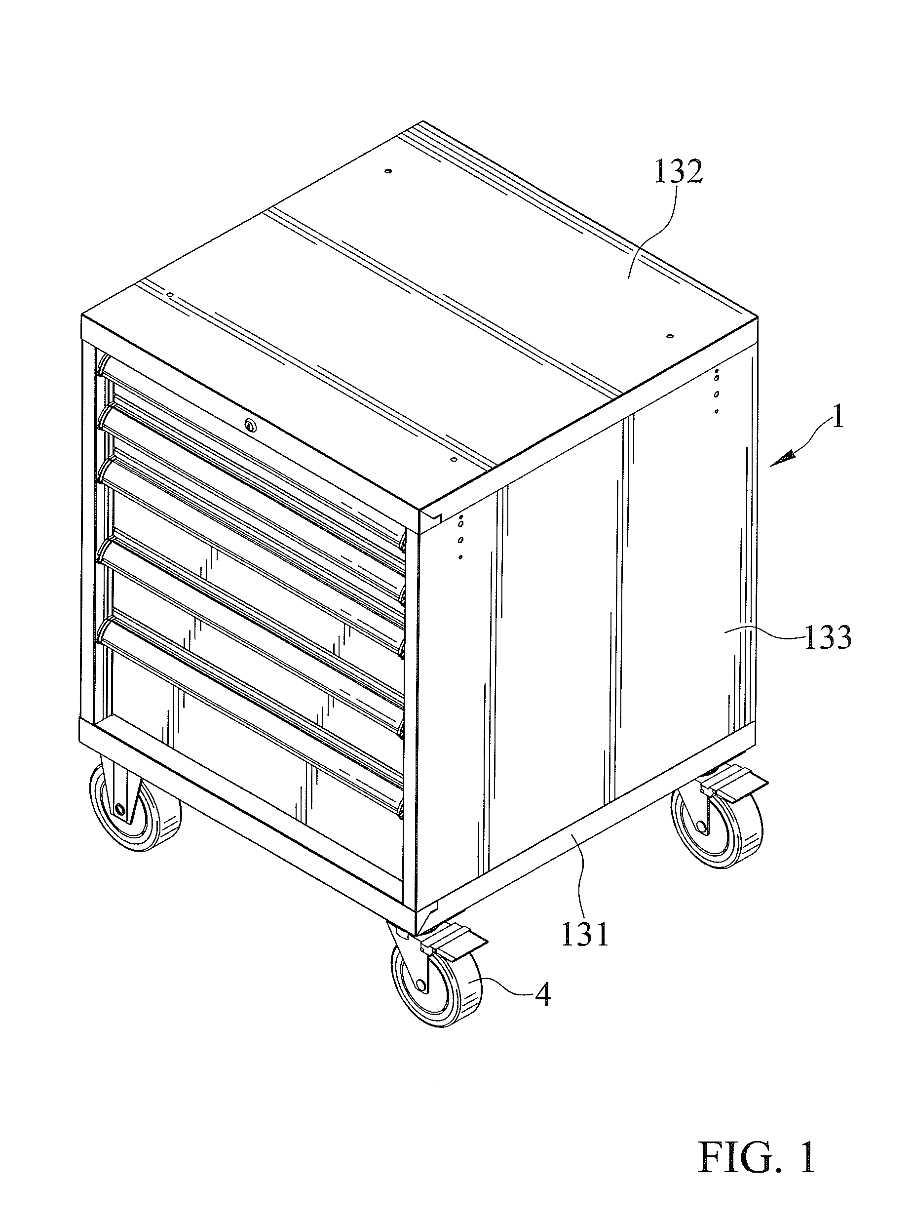
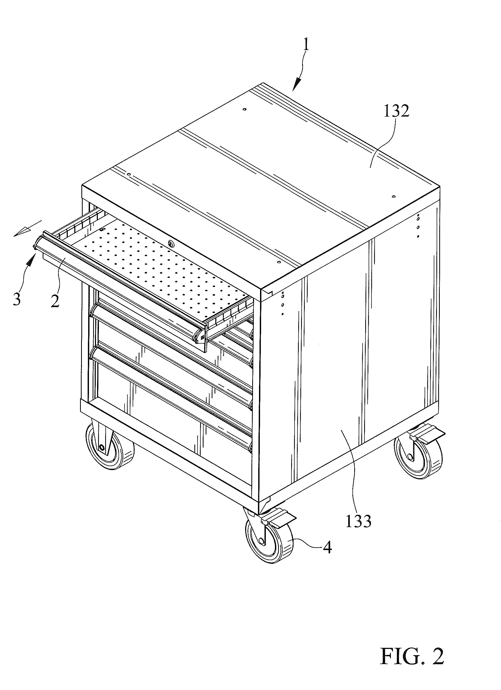
[0021]A tool cabinet 1 in accordance with the present invention includes a cabinet body, at least one drawer 2 received by the cabinet body, and at least one opening and closing device 3 engaged with the cabinet body and the at least one drawer 2, and a plurality of casters 4 mounted to the cabinet body.

[0022]The cabinet body has a bottom side 131, a top side 132, and a lateral side 133. The bottom and top sides 131 and 132 are disposed oppositely in a height direction of the cabinet body. The plurality of casters 4 is mounted to the bottom side 131 of the cabinet body. The plurality of casters 4 enable the tool cabinet 1 to be easily moved. Each of the plurality of casters 4 is...


PUM


Abstract

A tool cabinet includes a cabinet body, a drawer received by the cabinet body, and an opening and closing device engaged with the cabinet body and the drawer. The opening and closing device includes a first and second holder, a displacing member, a flipping member, and a biasing member. The displacing member is restrained by the first and second holders and is adapted to be inserted into a recessed structure defined by the cabinet body. The displacing member is biased by the biasing member. The flipping member is restrained by the first holder and is pivotal relative thereto. The displacing and flipping members include a first and second slant surface in contact with each other. Upon pivoting the flipping member, the displacing member is adapted to be moved. The drawer is prevented from being opened when the displacing member is inserted into the recessed structure.

Description

CROSS REFERENCE TO RELATED APPLICATION[0001]The present application is a continuation application of U.S. patent application Ser. No. 14 / 696,584 filed on Apr. 27, 2015, of which the disclosure is incorporated herein.BACKGROUND OF THE INVENTION[0002]1. Field of the Invention[0003]The present invention relates to a tool cabinet and, in particular, to a tool cabinet including at least one drawer and at least one drawer opening and closing device interacted with the at least one drawer and configured to be movable to a first position in which the at least one drawer can be pulled out, and to a second position in which the at least one drawer is locked and prevented from being pulled out.[0004]2. Description of the Related Art[0005]With reference to FIGS. 11 and 12 for a conventional drawer opening and closing device, the conventional drawer opening and closing device comprises a blocking member 41 disposed on a side of a cabinet 4, and a pivot member 51 pivotally installed to the front ...

Claims


Application Information

Patent Timeline
IPC IPC(8): A47B88/04B25H3/02B62B3/00A47B81/00A47B88/16
CPCA47B88/047A47B81/00B25H3/028B62B3/00A47B88/16B25H3/00B62B3/005E05B17/0008E05B65/46E05C1/14E05C9/002
Inventor CHANG, TING YU
Owner CHANG TING YU
Why Eureka
Try Eureka