Light Input-adjustable Window Shade

a technology of input adjustment and window shade, which is applied in the direction of door/window protective devices, buildings, building components, etc., can solve the problems of shortening the service life of the conventional increasing maintenance costs, and inconvenient use, so as to increase the convenience of use of the light input adjustment window shad

Inactive Publication Date: 2016-05-12
CHENG LI MING
View PDF2 Cites 32 Cited by
  • Summary
  • Abstract
  • Description
  • Claims
  • Application Information

AI Technical Summary

Benefits of technology

[0008]An objective of the present invention is to provide a light input-adjustable window shade including a level fixing device permitting a user to pull or push a weighting member to coil or uncoil a shade body, increasing use convenience of the light input-adjustable window shade.

Problems solved by technology

However, the user has to operate the actuation member 95 to move the shade body 93 upwards for coiling purposes, which is inconvenient to use.
Furthermore, the actuation member 95 is liable to damage (such as rusting of the bead chain or breakage of the pull cord) due to oxidation or brittlement, shortening the service life of the conventional light input-adjustable window shade 9 and increasing the maintenance costs.

Method used


Image

  • Light Input-adjustable Window Shade
  • Light Input-adjustable Window Shade
  • Light Input-adjustable Window Shade

Examples


first embodiment

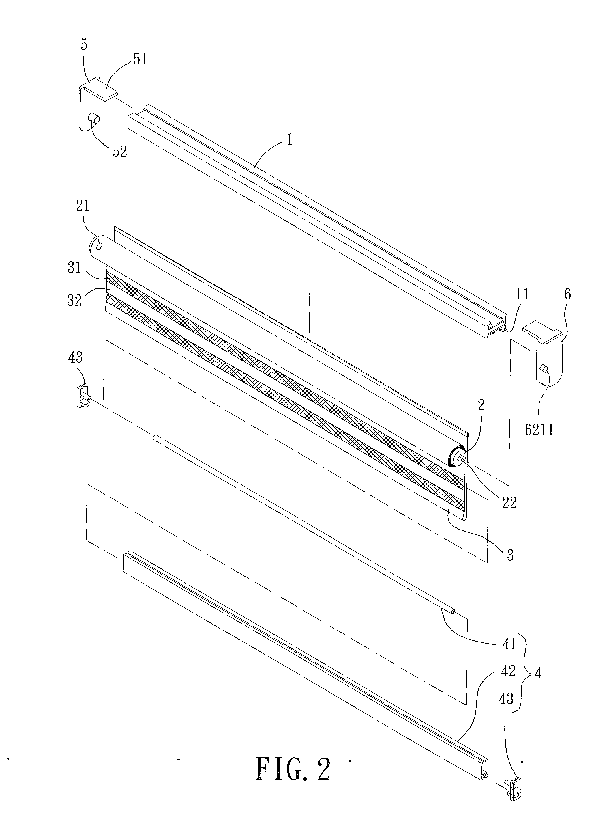
[0038]With reference to FIG. 2, a light input-adjustable window shade of a first embodiment according to the present invention includes a supporting member 1, a spool 2, a shade body 3, and a weighting unit 4. The supporting member 1 includes first and second ends respectively coupled to a positioning seat 5 and a level fixing device 6. The spool 2 includes first and second ends 21 and 22. The first end 21 of the spool 2 is rotatably mounted to the positioning seat 5. The second end 22 of the spool 2 is coupled to the level fixing device 6. The supporting member 1 further includes a coupling portion 11. The weighting unit 4 includes a rod 41. A first periphery of the shade body 3 is fixed to and coiled around the spool 2. The shade body 3 is wound around the rod 41. A second periphery of the shade body 3 is fixed to the coupling portion 11 of the supporting member 1.

[0039]The shade body 3 can include a plurality of light-impermeable portions 31 and a plurality of light-permeable por...

second embodiment

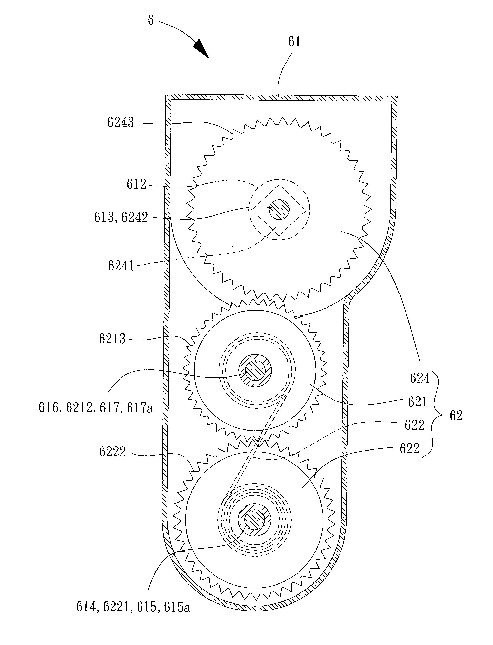
[0050]In the light input-adjustable window shade of the second embodiment according to the present invention, since the transmission unit 62 of the level fixing device 6 further includes the third transmission wheel 624, the magnitude of the first torque can be more easily designed to be equal to that of the second torque by adjusting the gear ratio between the third gear portion 6243 of the third transmission wheel 624 and the first gear portion 6213 of the first transmission wheel 621.

[0051]FIGS. 7 and 8 show a third embodiment of the light input-adjustable window shade according to the present invention modified from the second embodiment. In this embodiment, the first transmission wheel 621 includes a first gear portion 6213 on an outer edge thereof, and the second transmission wheel 622 includes a second gear portion 6222 on an outer edge thereof. The second gear portion 6222 meshes with the first gear portion 6213 such that the first transmission wheel 621 and the second trans...


PUM


Abstract

A light input-adjustable window shade includes a supporting member having first and second ends respectively coupled to a positioning seat and a level fixing device. The level fixing device includes a housing and a transmission unit mounted in the housing. The transmission unit includes a rotational shaft extending beyond the housing. A first end of a spool is rotatably mounted to the positioning seat. A second end of the spool is coupled to the rotational shaft of the level fixing device. A first periphery of a shade body is fixed to and coiled around the spool. The shade body is wound around a rod of a weighting unit. A second periphery of the shade body is fixed to a coupling portion of the supporting member.

Description

BACKGROUND OF THE INVENTION[0001]1. Field of the Invention[0002]The present invention relates to a light input-adjustable window shade and, more particularly, to a light input-adjustable window shade including a level fixing device.[0003]2. Description of the Related Art[0004]FIG. 1 shows a conventional light input-adjustable window shade 9 including a supporting rod 91, a spool 92, a blind sheet or a shade body 93, and a weighting rod 94. The supporting rod 91 is mounted to a top of a door or a window. A spool 92 is mounted to the supporting rod 91. An end of the shade body 93 is fixed to and coiled around the spool 92. The other end of the shade body 93 is wound around the weighting rod 94 and is coupled to the supporting rod 91. Thus, the shade body 93 is folded relative to the weighting rod 94 to form a dual-layer shade body structure permitting adjustment of the light input amount. An example of such a light input-adjustable window shade is disclosed in U.S. Pat. No. 7,267,156....

Claims


Application Information

Patent Timeline
Patent Type & Authority Applications(United States)
IPC IPC(8): E06B9/24
CPCE06B9/24E06B9/40E06B9/50E06B9/60E06B2009/2405
Inventor CHENG, LI-MING
Owner CHENG LI MING
Why Eureka
Try Eureka