Fire control with multiple user-selectable trigger profiles

a trigger profile and user-selectable technology, applied in the field of user-selectable trigger profiles, can solve the problems of reducing the safety of normal shooting and handling scenarios, impede rapid firing and high-precision bench firing, and the degree of unpredictability of the trigger, so as to achieve the effect of quick selection

Inactive Publication Date: 2016-05-12
HORCH ROBERT ADAM
View PDF28 Cites 35 Cited by
  • Summary
  • Abstract
  • Description
  • Claims
  • Application Information

AI Technical Summary

Benefits of technology

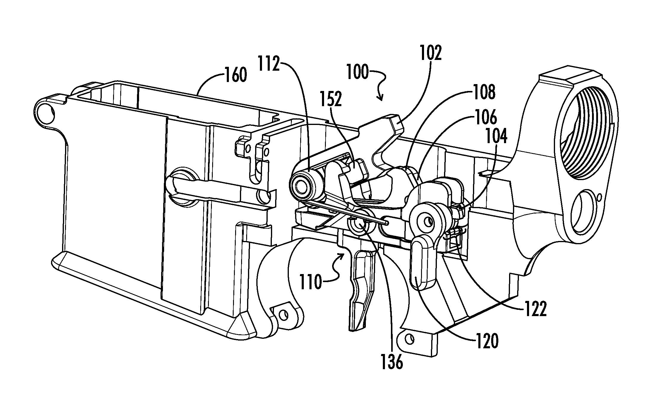
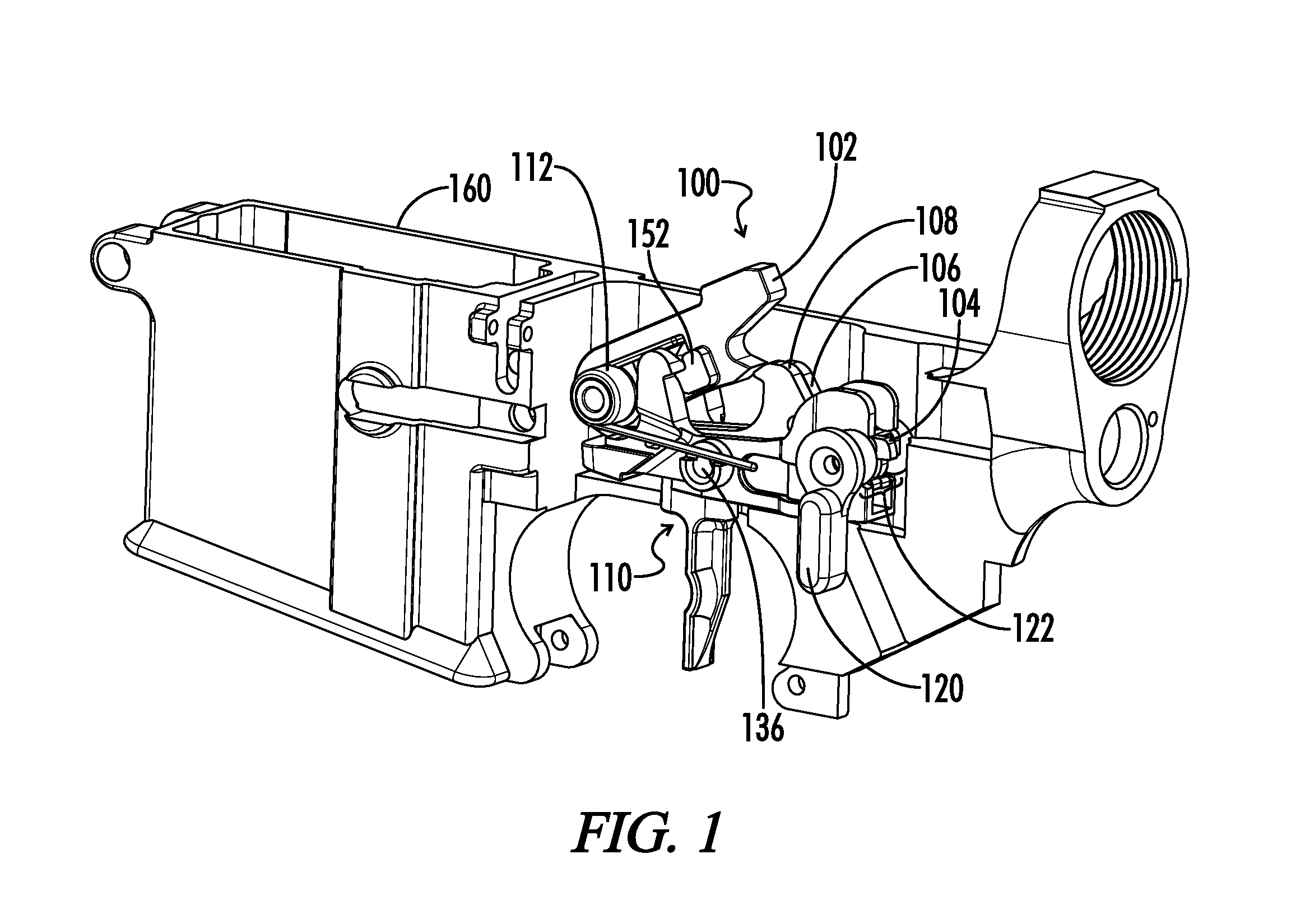
[0007]Aspects of the present invention enable a user to modify a trigger profile of a firearm by moving a safety / selector switch among three positions. In one embodiment, the trigger profiles achieved include safe, duty, and rapid fire. Alternatively, the trigger profiles achieved could include any of safe, duty, rapid fire, and precision. In one embodiment, the duty profile is implemented in a 2-stage design and the rapid fire profile is implemented by a 1-stage design to aid in ease of operation. Both types of trigger profiles mechanically coexist within the same rifle, and the operator can quickly select the appropriate trigger profile by operating the selector switch via a lever attached thereto.
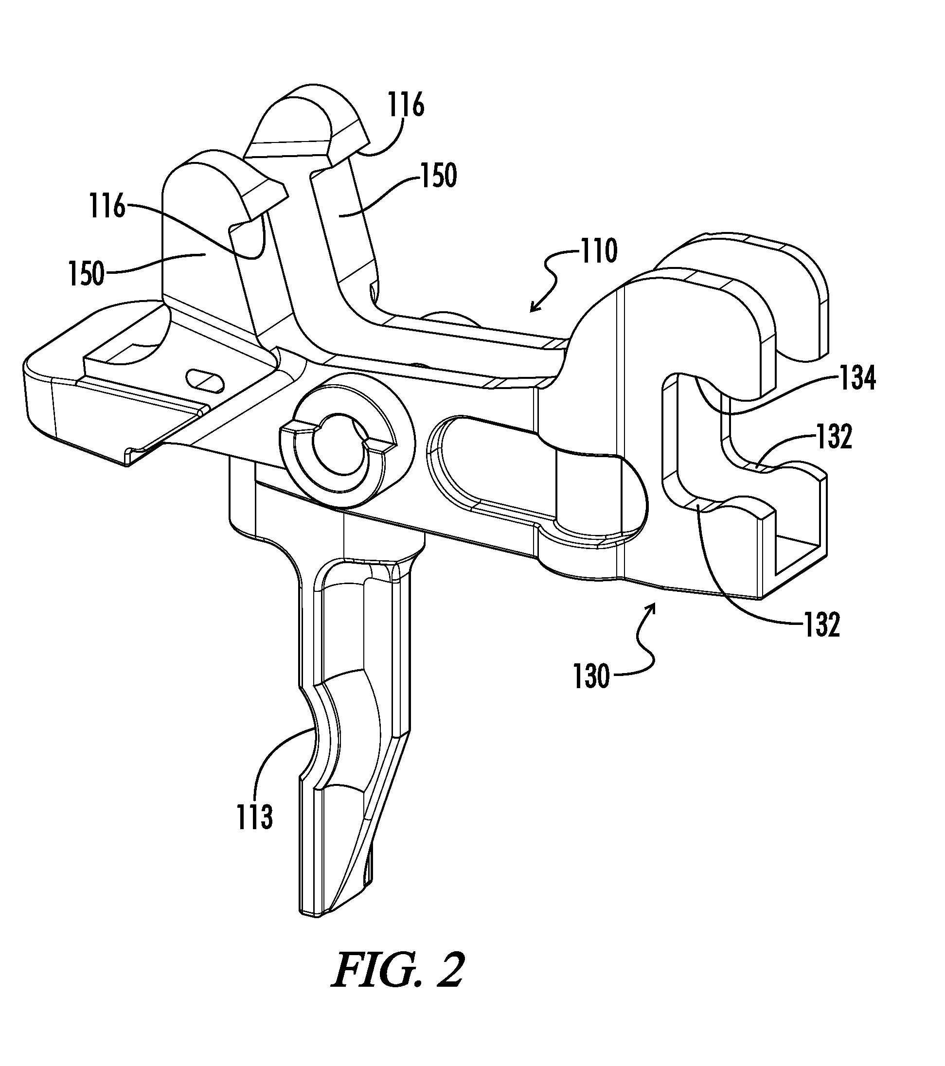
[0010]In another aspect, multiple modes of operation are achieved with a trigger, fire control selector switch, and at least two disconnectors. Referring to FIGS. 11 and 12, a trigger tang of the trigger engages selector switch to alter pretravel and overtravel differently depending on selector switch position. The selector switch includes a first set of cam surfaces intended to adjust pretravel and overtravel depending on selector switch position and a second set of cam surfaces intended to engage or disengage one or more disconnectors (see, for example, FIGS. 11 and 12). The compound trigger sear surface engages the hammer to adjust trigger pull weight depending on trigger pull distance (FIG. 8). The two disconnectors have a common pivot point (e.g., trigger pin) but each have different spring capture points, thereby creating differential torque on each disconnector (when seated in the trigger and using two disconnector springs of same stiffness). Alternatively, the disconnector springs may be at the same distance from the common pivot, but utilize 2 disconnector springs having different spring rates, or the operator can further the torque differential during trigger installation by using two springs of different stiffness. This torque differential contributes to the trigger pull weight difference between 1-stage and 2-stage modes of operation.

Problems solved by technology

However, these features impede rapid firing and high precision bench firing.
A rapid fire or precision trigger should have minimal pull weight and travel so as to be quick and effortless to operate, but such features add a degree of unpredictability to the trigger that reduces safety in normal shooting and handling scenarios.

Method used


Image

  • Fire control with multiple user-selectable trigger profiles
  • Fire control with multiple user-selectable trigger profiles
  • Fire control with multiple user-selectable trigger profiles

Examples


Embodiment Construction

[0039]While the making and using of various embodiments of the present invention are discussed in detail below, it should be appreciated that the present invention provides many applicable inventive concepts that can be embodied in a wide variety of specific contexts. The specific embodiments discussed herein are merely illustrative of specific ways to make and use the invention and do not delimit the scope of the invention.

[0040]To facilitate the understanding of the embodiments described herein, a number of terms are defined below. The terms defined herein have meanings as commonly understood by a person of ordinary skill in the areas relevant to the present invention. Terms such as “a,”“an,” and “the” are not intended to refer to only a singular entity, but rather include the general class of which a specific example may be used for illustration. The terminology herein is used to describe specific embodiments of the invention, but their usage does not delimit the invention, excep...


PUM


Abstract

A fire control group is capable of operating in multiple, user-selectable modes. The fire control group includes two disconnectors, a selector switch, and a trigger with a tang. The selector switch has a series of cams which interact with the tang of the trigger and surfaces of the two disconnectors to provide different hammer break points (i.e., distances from neutral), reset distances, overtravel distances, and pull weights, depending on a rotational position of the selector switch. In one embodiment, the fire control group is capable of a safe mode, a 2-stage trigger pull, and a 1-stage trigger pull.

Description

[0001]A portion of the disclosure of this patent document contains material that is subject to copyright protection. The copyright owner has no objection to the reproduction of the patent document or the patent disclosure, as it appears in the U.S. Patent and Trademark Office patent file or records, but otherwise reserves all copyright rights whatsoever.CROSS-REFERENCES TO RELATED APPLICATIONS[0002]This application claims priority to and hereby incorporates by reference in its entirety U.S. Provisional Patent Application Ser. No. 61 / 912,788 entitled “FIRE CONTROL GROUP WITH MULITPLE USER-SELECTABLE TRIGGER PROFILES” filed on Dec. 6, 2013.STATEMENT REGARDING FEDERALLY SPONSORED RESEARCH OR DEVELOPMENT[0003]Not ApplicableREFERENCE TO SEQUENCE LISTING OR COMPUTER PROGRAM LISTING APPENDIX[0004]Not ApplicableBACKGROUND OF THE INVENTION[0005]The present invention relates generally to fire control groups (i.e., trigger groups). More particularly, this invention pertains to fire control or ...

Claims


Application Information

Patent Timeline
Patent Type & Authority Applications(United States)
IPC IPC(8): F41A19/16F41A19/10F41A19/14F41A19/12
CPCF41A19/16F41A19/14F41A19/10F41A19/12
Inventor HORCH, ROBERT ADAM
Owner HORCH ROBERT ADAM
Why Eureka
Try Eureka