Structured granular composite materials, methods of fabrication thereof and applications thereof

a composite material and structure technology, applied in the field of granular composite materials, can solve the problems of limiting the user's field of view, affecting the use of the display, and a wide range of optical display architectures, etc., to achieve the effect of negligible absorption, high scattering efficiency and wavelength selectivity

Inactive Publication Date: 2016-05-19
UNIV OF CENT FLORIDA RES FOUND INC
View PDF0 Cites 0 Cited by
  • Summary
  • Abstract
  • Description
  • Claims
  • Application Information

AI Technical Summary

Benefits of technology

[0009]A critical optical component that may be integrated into a variety of optical systems is an optical display. Recent advances in optoelectronic device fabrication have produced a myriad of optical display architectures, not all of which are practical for field deployment within the context of a military application. Furthermore, most large-area optical displays are heavy, energy consuming and restricted in-practice to a rigid flat geometry. Indeed, such an optical display may block a user's field of view, which is an undesirable feature of most current embodiments. A transparent or opaque optical display that can provide 3D information depiction on a flat or curvilinear surface that is either opaque or transparent is thus clearly desirable. Such an optical display if possibly assembled in a field environment in a short period of time would introduce critical advantages for a range of national defense applications.
[0021]2) An optical display (or other optical apparatus) that can be permanent or assembled in the field in a short period of time (e.g., by spraying);

Problems solved by technology

Recent advances in optoelectronic device fabrication have produced a myriad of optical display architectures, not all of which are practical for field deployment within the context of a military application.
Furthermore, most large-area optical displays are heavy, energy consuming and restricted in-practice to a rigid flat geometry.
Indeed, such an optical display may block a user's field of view, which is an undesirable feature of most current embodiments.

Method used


Image

  • Structured granular composite materials, methods of fabrication thereof and applications thereof
  • Structured granular composite materials, methods of fabrication thereof and applications thereof
  • Structured granular composite materials, methods of fabrication thereof and applications thereof

Examples


Embodiment Construction

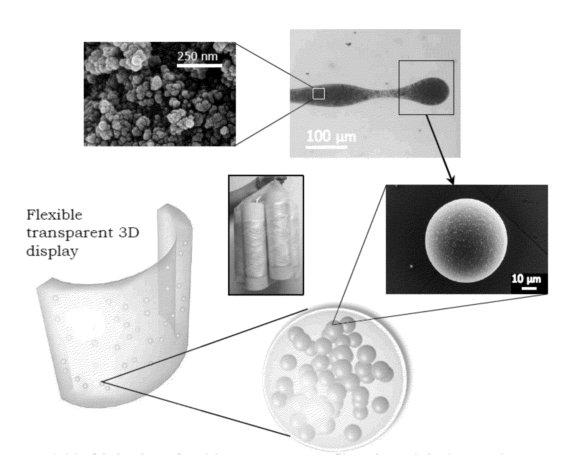
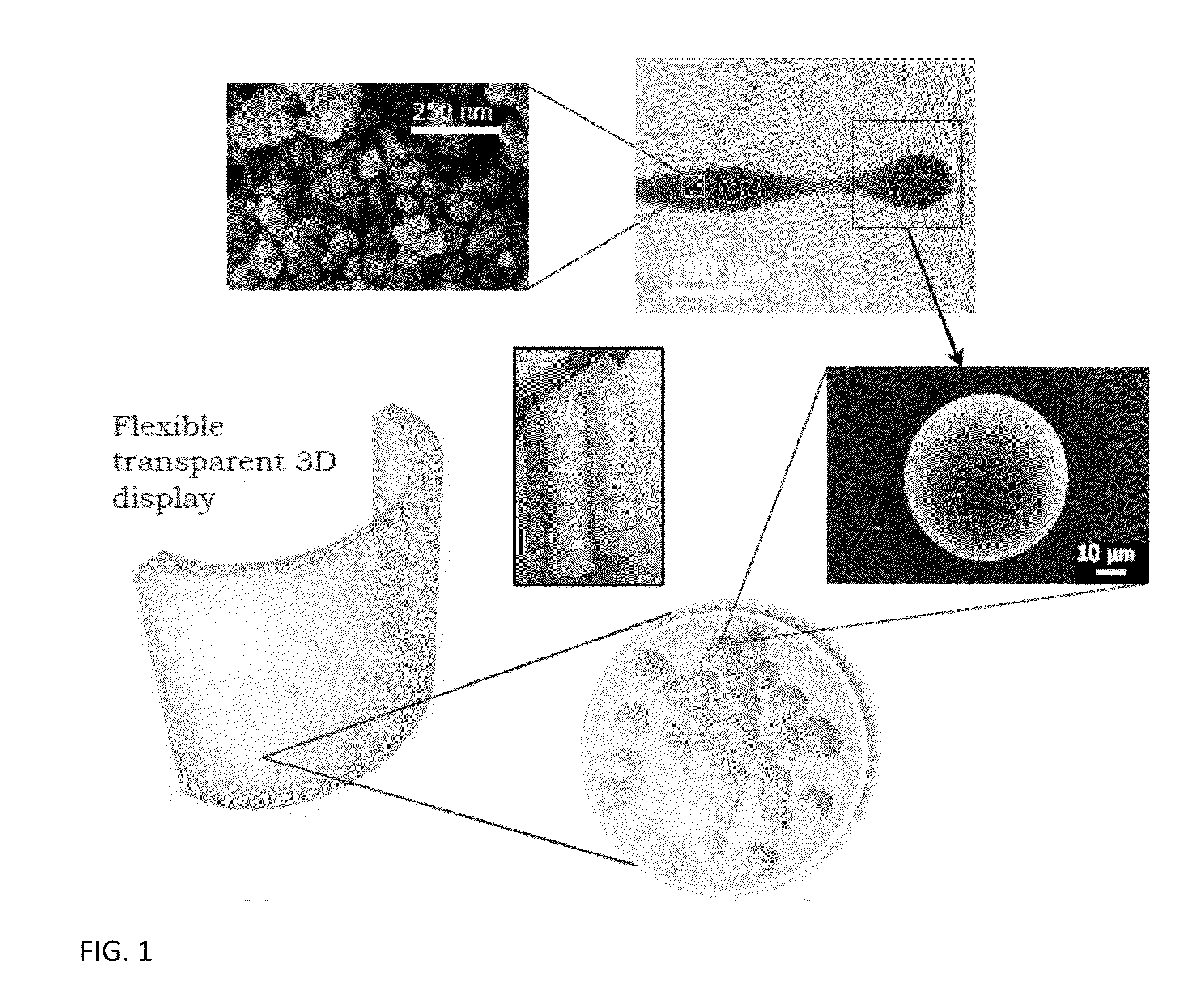
[0043]The embodiments provide an optical material feedstock that may be processed to form a plurality of composite optical elements that may be further incorporated into an optical apparatus. The composite optical elements in turn include a primary optically active component (i.e., generally a primary sphere) into which is contained a plurality of secondary optically active components (i.e., generally a plurality of secondary spheres of dimensions smaller than the primary sphere.

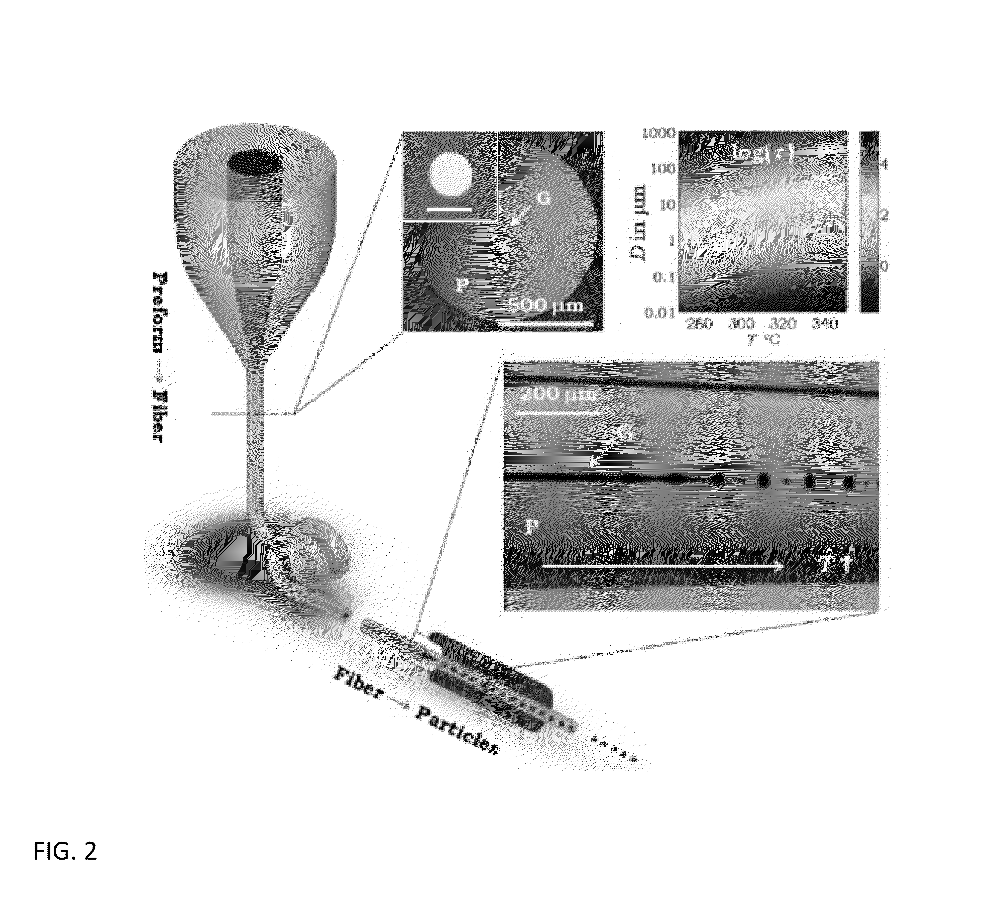
[0044]The embodiments also provide a method for producing the composite optical element from the optical material feedstock. The embodiments also provide the particular optical apparatus that results from the methods. Such a particular optical apparatus desirably comprises an optical display.

[0045]Within the embodiments a particular optical material feedstock includes a bulk carrier material and a plurality of secondary optically active components included within the bulk carrier material. The bulk carrier m...


PUM

PropertyMeasurementUnit
core radiiaaaaaaaaaa
optical transparencyaaaaaaaaaa

Abstract

A structured granular optical component for use within an optical apparatus includes a primary optically active component comprising a first optical material and a secondary optically active component contained within the first optically active component and comprising a second optical material different than the first optical material. The first optical material and the second optical material are selected to influence scattering. When incorporated into a macroscopic optical apparatus the structured granular optical component provides enhanced performance.

Description

CROSS-REFERENCE TO RELATED APPLICATION[0001]This application derives from, and is related to, U.S. Provisional Patent Application Ser. No. 62 / 079,907, filed 14 Nov. 2014 and titled “Structural Granular Composite Materials, Methods of Fabrication Thereof and Applications Thereof,” the contents of which are incorporated herein fully by reference.STATEMENT OF GOVERNMENT INTEREST[0002]Research that lead to the embodiments as described herein, and the invention as claimed herein, was funded by the United States Defense Advanced Research Projects Agency (DARPA) under contract DARPA-BAA-14-56. The United States Government has rights in the invention as claimed herein.BACKGROUND[0003]1. Field[0004]The embodiments relate generally to granular composite materials. More particularly the embodiments relate to high performance structured granular composite materials, methods for fabrication thereof and applications thereof.[0005]2. Description of the Related Art[0006]The presence and use of opti...

Claims


Application Information

Patent Timeline
Patent Type & Authority Applications(United States)
IPC IPC(8): G02B5/02D01D5/08
CPCG02B5/0242D10B2401/20D01D5/08D01D5/12D01F1/10D01F6/00D01F8/04
Inventor ABOURADDY, AYMANDOGARIU, ARISTIDEKAUFMAN, JOSHUANARAGHI, ROXANA R.SUKHOV, SERGEYTAN, FELIX
Owner UNIV OF CENT FLORIDA RES FOUND INC
Why Eureka
Try Eureka