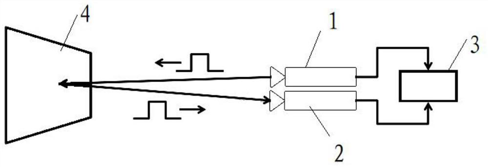
A tof depth camera

A depth camera and grayscale technology, applied in instruments, measuring devices, and re-radiation, can solve the problems of large light energy, large measurement error, and small shutter exposure energy, so as to reduce the number of opening times, reduce power consumption, and ensure The effect of stability

Active Publication Date: 2022-02-11
HANGZHOU GUANGPO INTELLIGENT TECH CO LTD
View PDF6 Cites 0 Cited by
  • Summary
  • Abstract
  • Description
  • Claims
  • Application Information

AI Technical Summary

Problems solved by technology

[0010] Aiming at the deficiencies of the prior art, the purpose of the present invention is to solve the measurement problem caused by the excessive concentration of reflected light in the existing TOF depth camera when the light energy received by the camera detector is too large during short distance measurement. The error is relatively large. By designing a three-shutter heterogeneous scheme, the exposure energy of the shutter corresponding to the short distance is small, and the exposure energy of the shutter corresponding to the long distance, so that both long and short distances can work in a normal state.

Method used


Image

  • A tof depth camera
  • A tof depth camera
  • A tof depth camera

Examples


Embodiment 1

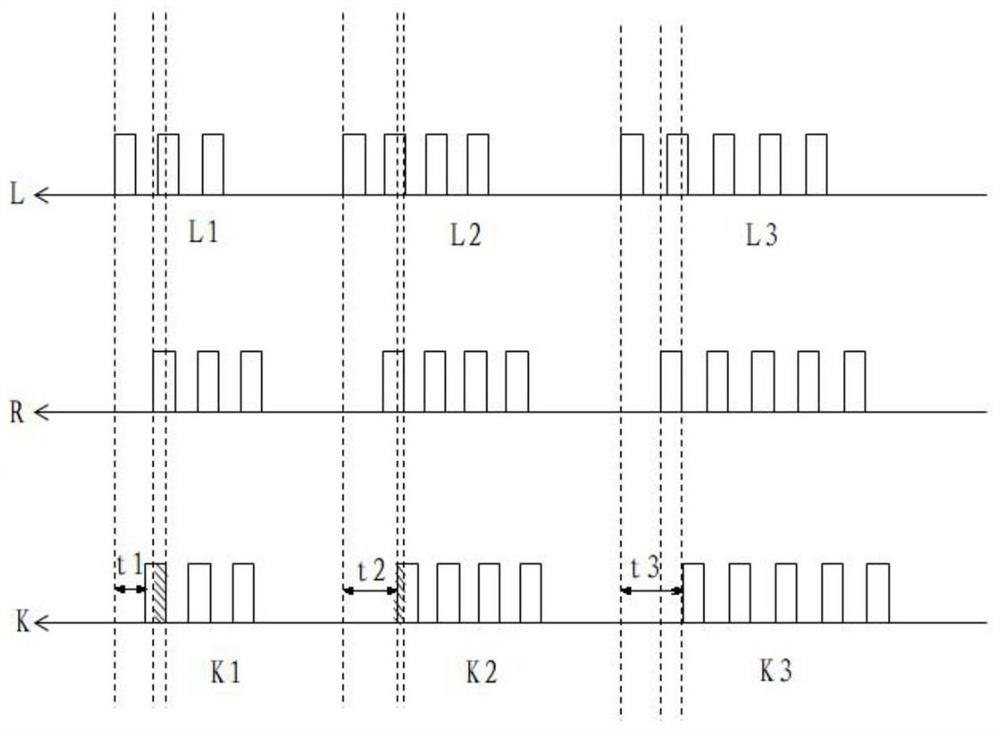
[0055] In the first embodiment, the configuration of the pulsed light source and three shutters can be found in image 3 . In this embodiment, the number of openings of the first shutter is equal to the number of pulses of the first pulse, the number of openings of the second shutter is equal to the number of pulses of the second pulse, and the number of times of opening of the third shutter is equal to the number of pulses of the third pulse , wherein the first pulse has the smallest number of pulses, and the third pulse has the largest number of pulses, so that the grayscale of the image acquired by the imaging and detection device under the first pulse is the smallest, and the grayscale of the image acquired under the third pulse is the largest. In this embodiment, the light source and the shutter are adjusted at the same time to obtain different gray scales measured at different distances. The pulse light source and shutter opening times are modulated according to the dist...

Embodiment 2

[0057] In the second embodiment, the configuration of the pulsed light source and three shutters can be found in Figure 7 . In this embodiment, the number of pulses of the first pulse, the second pulse and the third pulse is equal, the number of openings of the first shutter is the least, and the number of openings of the third shutter is the largest, so that the imaging and detection device can operate under the first pulse The gray scale of the acquired image is the smallest, and the gray scale of the image acquired under the third pulse is the largest. In this embodiment, the gray value of the image measured at different distance intervals is controlled by controlling the number of times the shutter is opened. The number of times the pulse light source is turned on keeps the same configuration for each imaging, which can simplify part of the control difficulty.

Embodiment 3

[0059] In the third embodiment, the configuration of the pulsed light source and three shutters can be found in Figure 8 . In this embodiment, the opening times of the first shutter, the second shutter and the third shutter are equal, the number of pulses of the first pulse is the least, and the number of pulses of the third pulse is the largest, so that the imaging and detection device can operate under the first pulse The gray scale of the acquired image is the smallest, and the gray scale of the image acquired under the third pulse is the largest. In this embodiment, the gray value of the image measured at different distance intervals is controlled by controlling the number of times the pulse light source is turned on. The opening times of the three shutters keep the same configuration for each imaging, and only the pulse light source is modulated, which can simplify the shutter requirements.


PUM


Abstract

The present invention proposes a TOF depth camera, including a pulsed light source, imaging and detection devices, and a control module, the control module controls the number of pulses and / or corresponding pulses of the first pulse, the second pulse and the third pulse emitted by the pulsed light source The number of openings of the first shutter, the second shutter and the third shutter makes the imaging and detection devices work in the linear region under the three shutters. The present invention adopts a 3-shutter heterogeneous method, and sets 3 shutters with different configuration schemes on the imaging and detectors. These three shutters have different delay times and different opening times, so that in different measurement intervals, each shutter The exposure amount can be within the normal working range of the detector, so as to ensure the compatibility of short distance and long distance.

Description

technical field [0001] The invention relates to a distance measurement device, in particular to a TOF depth camera for realizing distance measurement by detecting time-of-flight (TOF). Background technique [0002] According to different depth measurement principles, depth cameras are generally divided into: time-of-flight method, structured light method, and binocular stereo vision method. Flight time is literally translated from Time of Flight, referred to as TOF. The basic principle is to continuously emit light pulses (generally invisible light) to the object to be observed, and then use the sensor to receive the light returned from the object, and obtain the target object distance by detecting the flight (round trip) time of the light pulse. [0003] The light source modulation methods of the existing Time of Flight (TOF) depth cameras are mainly divided into two categories: one is the continuous wave phase detection method, which uses continuous periodic waveform ligh...

Claims


Application Information

Patent Timeline
Patent Type & Authority Patents(China)
IPC IPC(8): G01S17/10G01S17/894G01S7/481
CPCG01S17/10G01S7/481
Inventor 宋复俊陈宇杨金峰王弼张合勇
Owner HANGZHOU GUANGPO INTELLIGENT TECH CO LTD
Why Eureka
Try Eureka