Device for tying shoes

a shoelace and device technology, applied in the field of shoelace structure, can solve the problems of increasing manufacturing cost, easy loosening of shoelace knots, and difficult manufacturing, and achieve the effect of convenient user wear of footwear, avoiding loosening of shoelace knots, and quick wearing of footwear

Inactive Publication Date: 2016-05-26
DAE SUNG SILICONE IND
View PDF0 Cites 3 Cited by
  • Summary
  • Abstract
  • Description
  • Claims
  • Application Information

AI Technical Summary

Benefits of technology

[0012]Accordingly, the present invention has been made to solve the aforementioned problem occurring in the prior art, and it is an object of the present invention to provide a footwear fastening structure configured such that it can be used in replacement of a shoelace by being simply engaged in shoelace holes or eyelets formed on the footwear in a press-fit manner so that the necessity for knotting the shoelace is eliminated, making it possible for a user to rapidly wear the footwear, and a risk of loosening of the shoelace knot is avoided, making it easy for the user to wear the footwear.

Problems solved by technology

However, such a conventional band member entails a problem in that after the band member is tied and knotted, its knot is easily loosened due to shaking caused by motion of a user's ankle while he or she is walking.
The prior art 1, however, encounters a problem in that the shoelace member has a plurality of resin projections attached to the top and bottom surfaces thereof at its entirety, thus making it difficult to manufacture and increasing the manufacturing cost.
However, the prior arts 1 and 2 still involve problems in that since a shoelace knot loosing-preventive structure for tying the band member is complicated, the number of the manufacturing processes is increased, and in that it is required that the shoelace should be tieably engaged in all the shoelace holes or eyelets and then be lastly knotted, thus making the knotting process inconvenient.

Method used


Image

  • Device for tying shoes
  • Device for tying shoes
  • Device for tying shoes

Examples


first embodiment

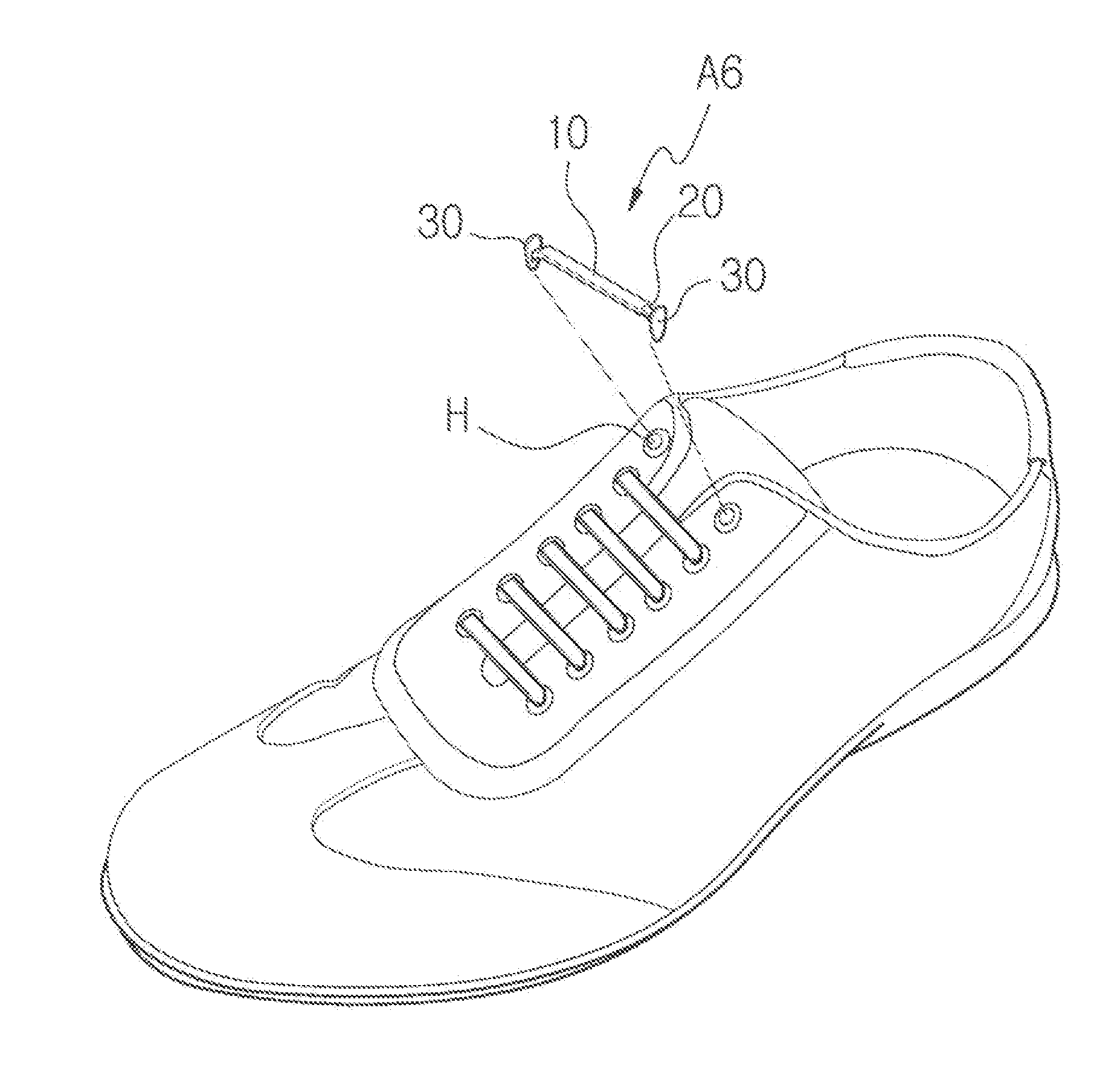
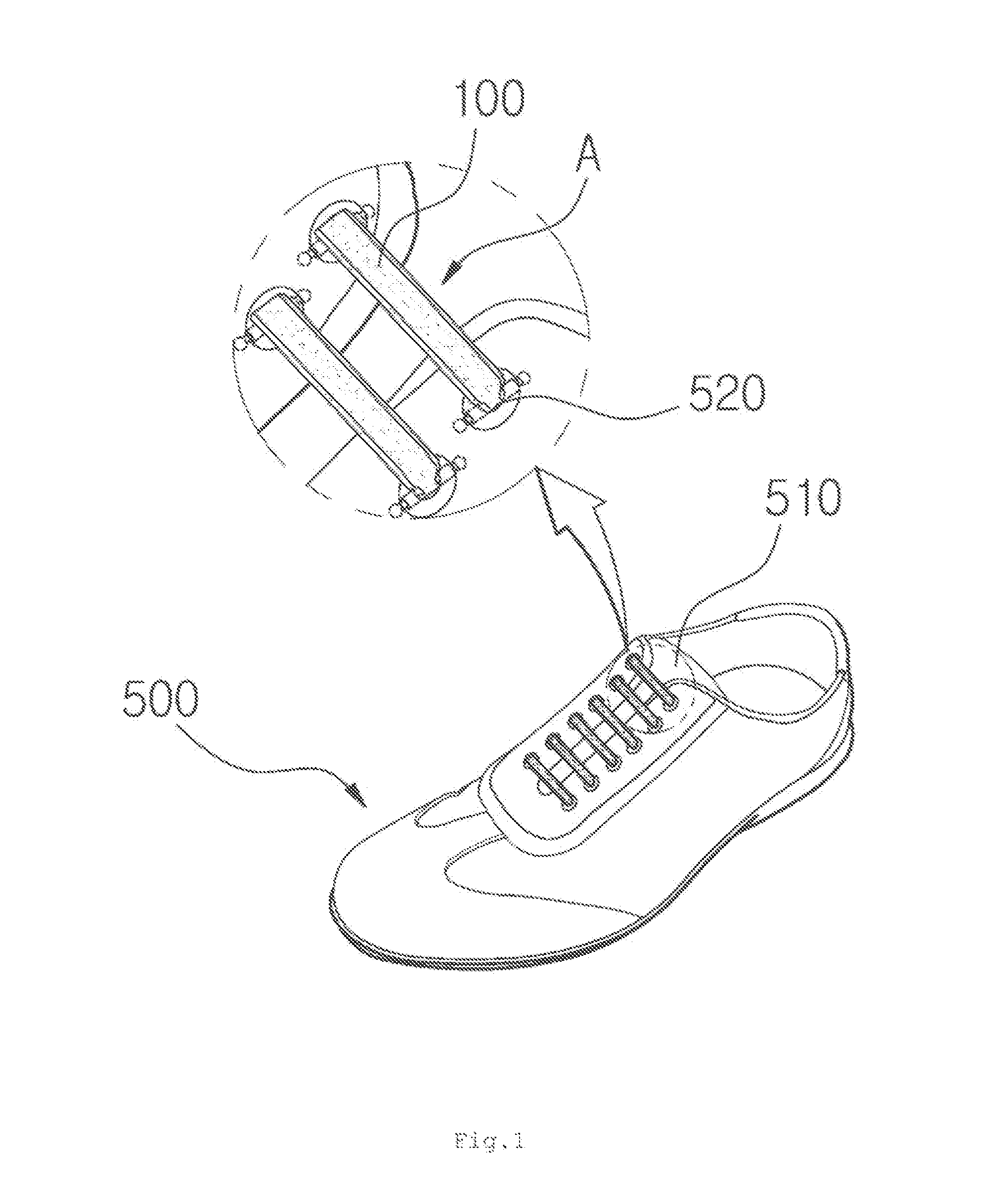
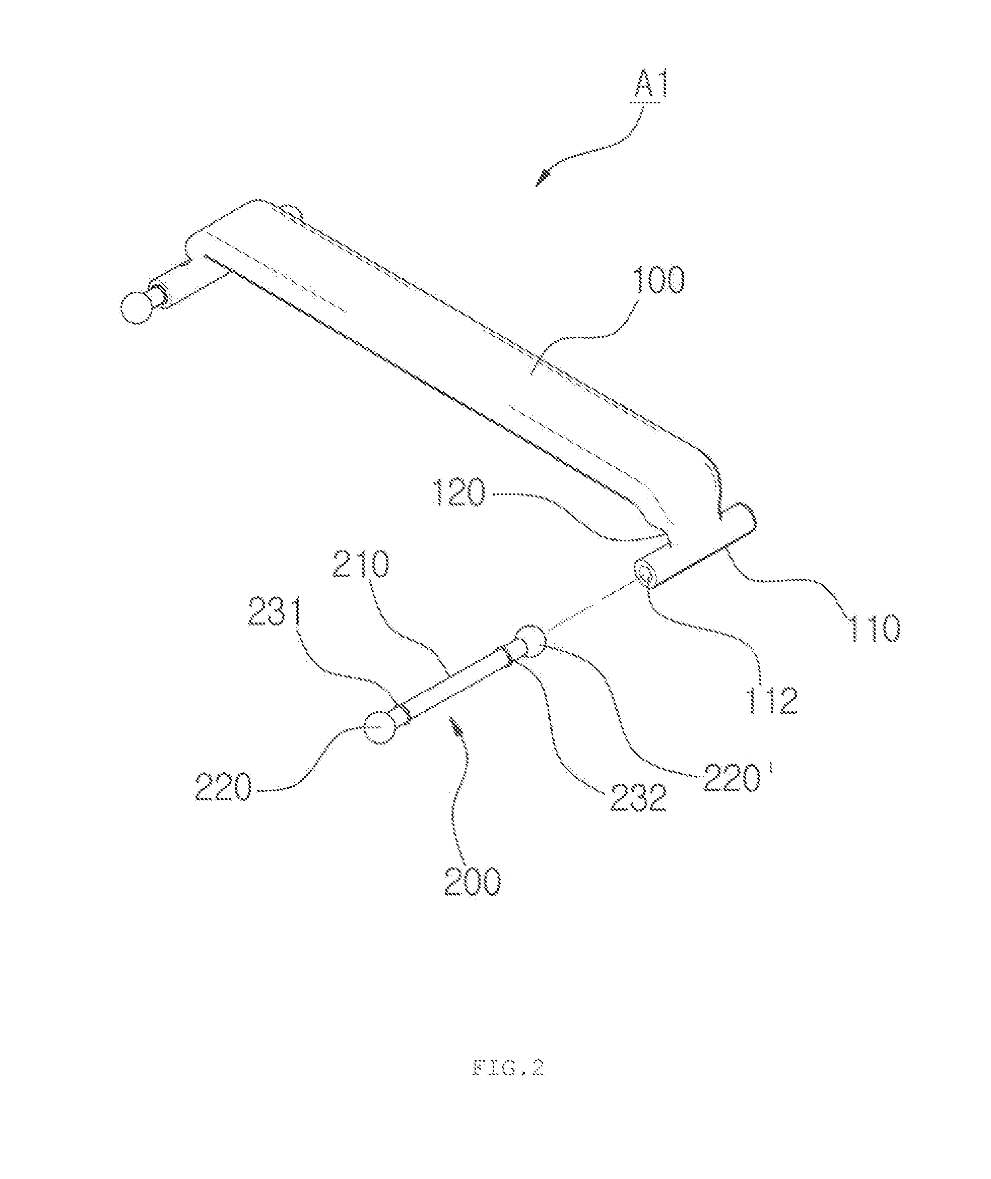
[0049]The footwear fastening structure A1 according to the present invention is configured such that it is tieably engaged in shoelace holes or eyelets of a shoe or sports shoe so as to fasten the shoe or the sports shoe tightly on a user's foot when he or she wears the shoe, the footwear fastening structure including: a band member 100 formed to have a predetermined length and having a pair of opposed engagement parts 110 respectively formed at both ends thereof, and a pair of opposed pin members 200 coupled to the engagement parts 110 of the band member 100 so as to be inserted into and hookingly fixed to the shoelace holes 520 of the shoe 500.

[0050]The band member 100 is formed to have a predetermined length using a material which is flexible and harmful to the human body such as rubber or silicon. The band member 100 can be largely divided into a rod shape and a strip shape depending on the kind of the shoe.

[0051]In other words, an elongated rod-like band member is applied to sh...

second embodiment

[0058]In the meantime, as shown in FIG. 4, a footwear fastening structure A2 according to the present invention is configured such that it is tieably engaged in shoelace holes or eyelets 520 of a shoe or sports shoe so as to fasten the shoe or the sports shoe tightly on a user's foot when he or she wears the shoe, the footwear fastening structure including: a band member 100 formed to have a predetermined length and having a pair of opposed engagement parts 110a respectively formed at both ends thereof, and a pair of opposed pin members 200 coupled to the engagement parts 110a of the band member 100 so as to be inserted into and hookingly fixed to the shoelace holes 520 of the shoe 500. The engagement part 110a is formed in a curved shape which is bent to have a low curvature.

[0059]Accordingly, the pin member 200a is formed in a curved shape which is bent to have a low curvature.

[0060]Thus, the bent engagement parts 110a are formed at the lower portions of the both ends of the band ...

third embodiment

[0073]In the meantime, as shown in FIGS. 5 to 7, a footwear fastening structure A3 according to the present invention is configured such that it is tieably engaged in shoelace holes or eyelets 520 of a shoe or sports shoe so as to fasten the shoe or the sports shoe tightly on a user's foot when he or she wears the shoe, the footwear fastening structure including: a band member 100 formed to have a predetermined length and having a pair of opposed engagement parts 110b respectively formed at both ends thereof, and a pair of opposed pin members 200 coupled to the engagement parts 110b of the band member 100 so as to be inserted into and hookingly fixed to the shoelace holes 520 of the shoe. The engagement part 110b is oriented vertically with respect to the ground surface.

[0074]Thus, the pin member 200b is fittingly coupled to the engagement part in a vertical direction and is moved vertically so that the pin member 200b can be fittingly engaged in the shoelace holes 520.

[0075]A metho...


PUM


Abstract

The present invention relates to a footwear fastening structure. The footwear fastening structure is configured such that it is tieably engaged in shoelace holes or eyelets of a shoe or sports shoe so as to fasten the shoe or the sports shoe tightly on a user's foot when he or she wears the shoe, the footwear fastening structure comprising: a band member formed to have a predetermined length and having a pair of opposed engagement parts respectively formed at both ends thereof; and a pair of opposed pin members coupled to the engagement parts of the band member so as to be inserted into and hookingly fixed to the shoelace holes of the shoe.

Description

CROSS-REFERENCE TO RELATED APPLICATION[0001]This application is a Section 371 National Stage application of International Application No. PCT / KR2014 / 010413, filed Nov. 3, 2014, the contents of which is hereby incorporated by reference in its entirety.TECHNICAL FIELD[0002]The present invention relates to a footwear fastening structure. More particularly, the present invention relates to footwear fastening structure which can be used in replacement of a shoelace used to be tied to footwear and can eliminate the necessity for knotting a shoelace.BACKGROUND[0003]In general, a band member tieably engaged in a plurality of shoelace holes or eyelets formed on footwear such as sports shoes or shoes has a circular or elliptical cross-section and is woven with fabric into a predetermined length.[0004]The multiple shoelace holes or eyelets are formed on an upper portion of the footwear in such a manner as to be symmetrically arranged at both sides of the upper portion.[0005]Thus, the band memb...

Claims


Application Information

Patent Timeline
Patent Type & Authority Applications(United States)
IPC IPC(8): A43C11/22A43C5/00
CPCA43C5/00A43C11/22A43C11/004
Inventor KIM, BYUNG-KI
Owner DAE SUNG SILICONE IND
Why Eureka
Try Eureka