Prosthetic socket suspension device embodiments

a technology of suspension device and prosthetic socket, which is applied in the direction of prosthesis, transportation and packaging, paper/cardboard containers, etc., can solve the problems of air leakage into space, common imperfections of the sealing seal, and air leakage past the liner seal

Inactive Publication Date: 2016-05-26
LIM INNOVATIONS
View PDF2 Cites 31 Cited by
  • Summary
  • Abstract
  • Description
  • Claims
  • Application Information

AI Technical Summary

Benefits of technology

[0008]Embodiments of the provided technology are directed to a prosthetic socket suspension device as well as methods of fabricating, and custom reshaping of the device to be appropr...

Problems solved by technology

However, the seal is commonly imperfect, and some air can leak past the liner seal, and into the space between the ...

Method used


Image

  • Prosthetic socket suspension device embodiments
  • Prosthetic socket suspension device embodiments
  • Prosthetic socket suspension device embodiments

Examples


embodiment 120

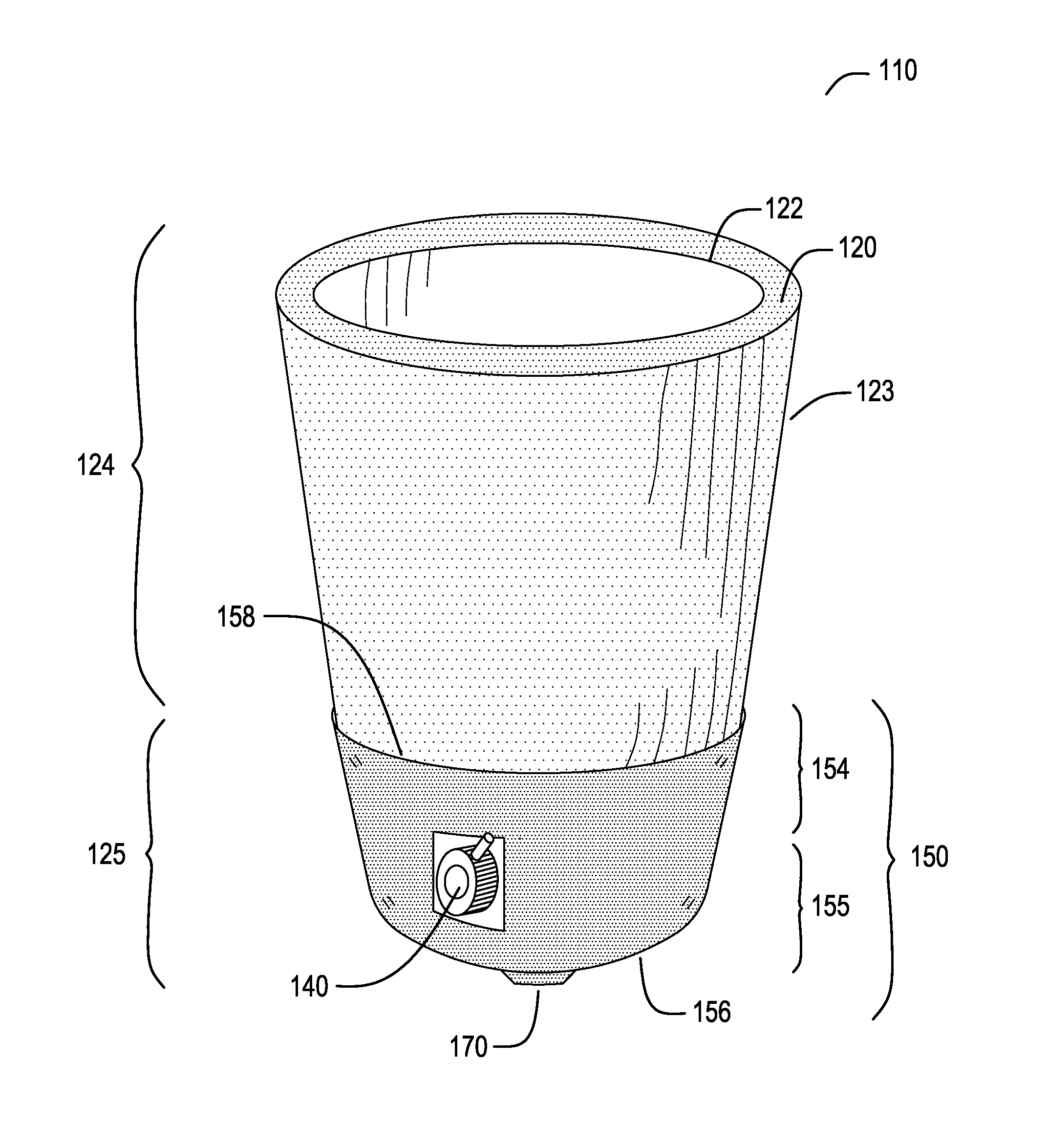
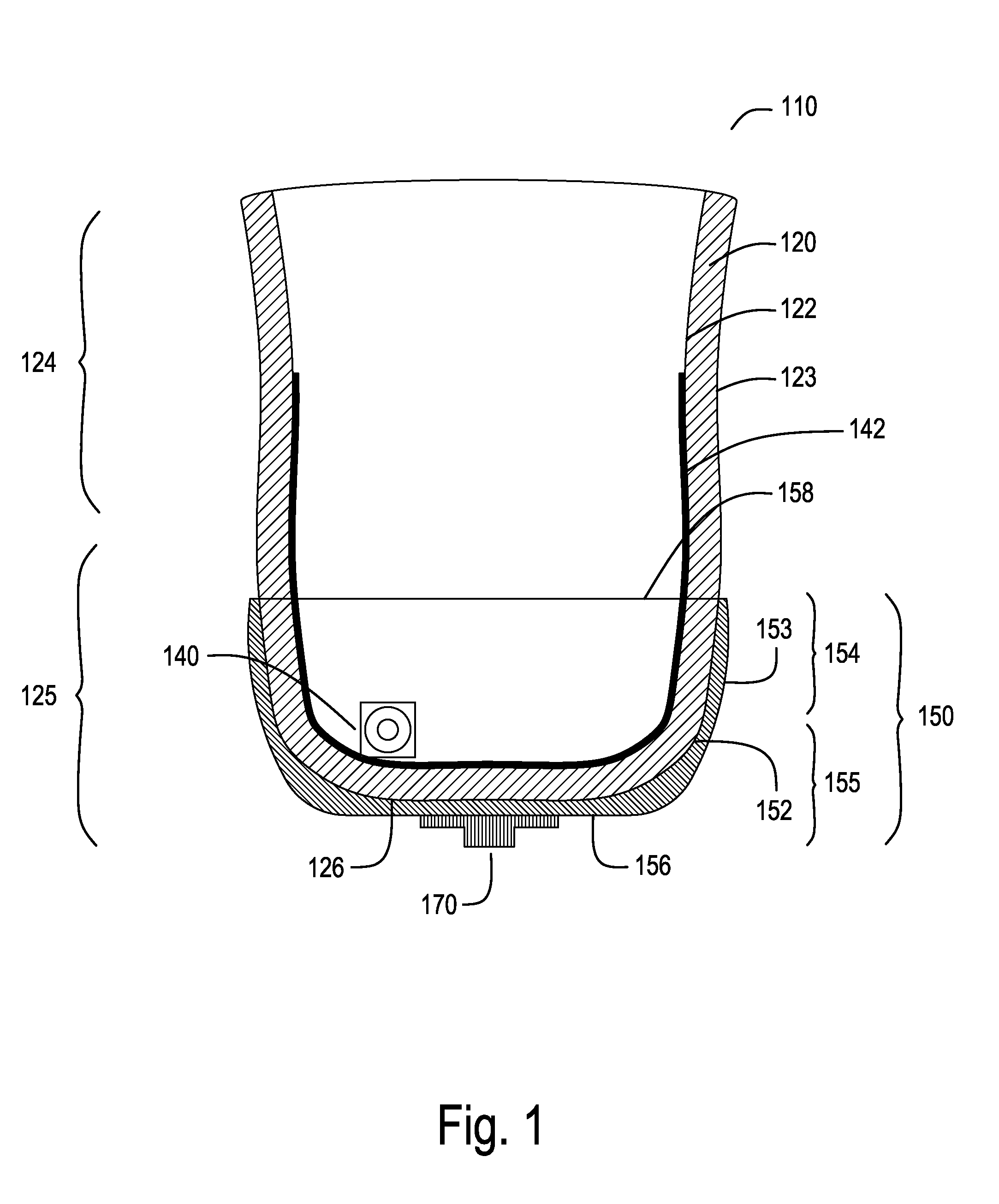
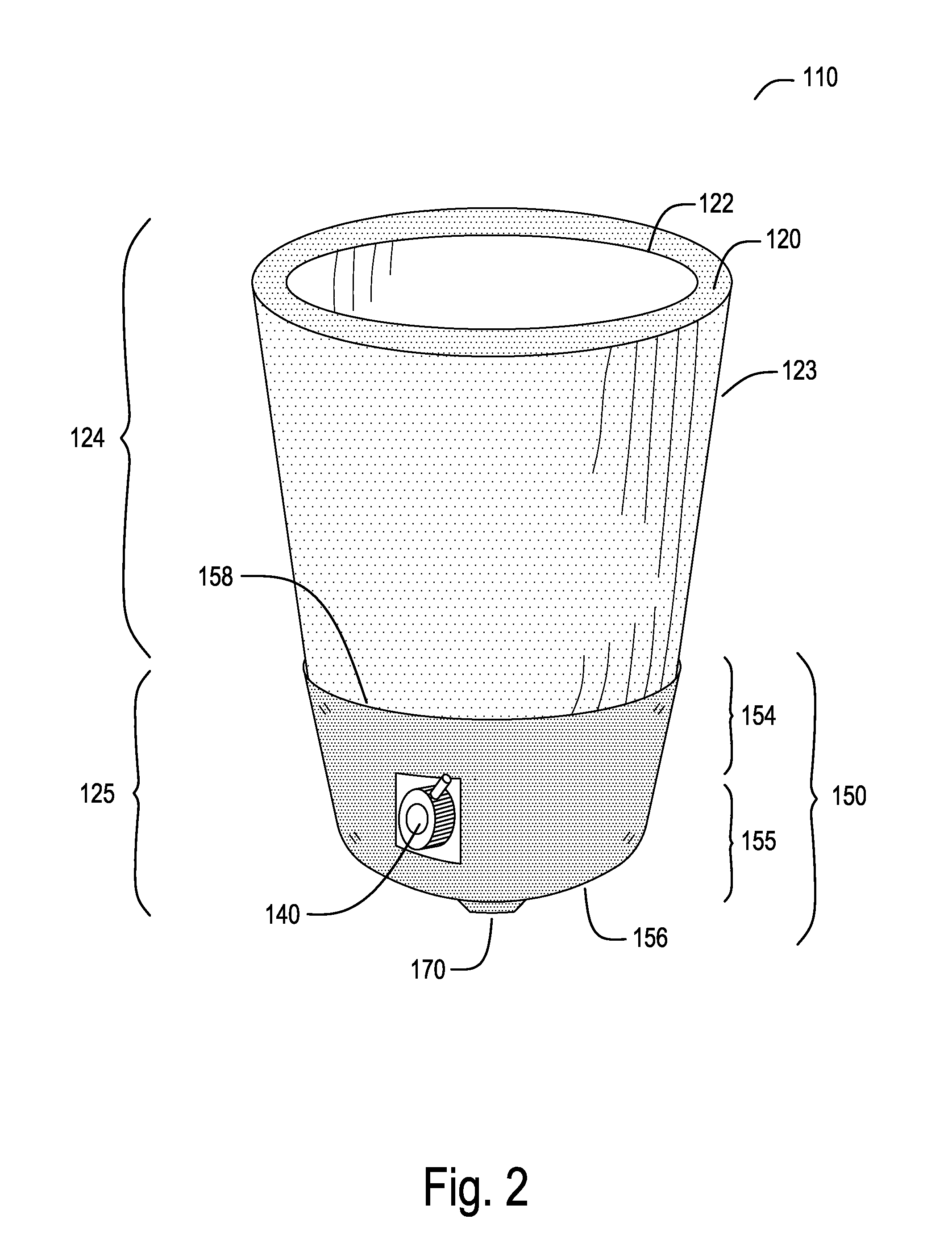
[0052]FIGS. 1 and 2 show a cross sectional side view and an upper perspective view, respectively, of an embodiment of a prosthetic device suspension device or supportive prosthetic socket liner 110 that includes a liner garment portion 120 disposed within a thermoplastic distal cup portion 150, the liner garment and distal cup being bonded together. The liner garment embodiment 120 has an internal surface 122, an external surface 123, a proximal portion 124, a distal portion 125, and a distal end 126. Suspension device embodiments further include a gel or elastomeric portion, and may include a fluid transport substrate portion. Other features of suspension device 110 include a distal fluid exit port 140 that provides a fluid escape route from within the confines of liner garment 120, through distal cup 150, and into the external environment. Distal fluid exit port 140 may be disposed at any suitable location in the distal portion 125 of liner garment 120 and the corresponding site i...

embodiment 150

[0054]Thermoplastic distal cup embodiment 150 has an internal surface 152, an external surface 153, a proximal portion 154, a proximal circumferential edge 158, a distal portion 155, and a distal end 156. A layer of bonding material, such as a silicon adhesive, and a padding or filler material may be disposed between liner garment 120 and distal cup 150.

[0055]Related embodiments and variations of the embodiments shown in FIGS. 1-2 are described in detail below. Some particular embodiments of suspension device 110, for example, have a bulbous distal end, as defined primarily by the shape of distal cup 150. Bulbous embodiments are shown in FIGS. 3-4. Bulbous suspension device embodiments are not being given a separate label identifier in this disclosure because, in fact, shapes of the distal cup can vary in a continuum from straight cylindrical or even slightly tapering conical to a pronounced bulbous shape. Such variations may occur both in stock inventory shapes and / or may arise dur...


PUM

PropertyMeasurementUnit
Temperatureaaaaaaaaaa
Angleaaaaaaaaaa

Abstract

Embodiments of the technology include a prosthetic socket suspension device having a distal cup portion and a liner garment portion, these two portions being bonded together. In various embodiments, a distal cup may be disposed within a liner, a liner may be disposed within a distal cup, and a distal cup may be disposed between distally bifurcated internal and an external layers of a liner. Distal cup are sized and shaped to accommodate a distal portion of a residual limb of a patient. Distal cup embodiments may be formed from either a thermoplastic or thermoset plastic composition. Thermoplastic cup embodiments may be thermally reformed around the distal portion of the limb so as to create a highly conformal fit. Embodiments of the technology further include methods fabricating the prosthetic suspension device, and methods of thermally reforming the suspension device so as to fit a distal aspect of the residual limb of a patient.

Description

CROSS-REFERENCE TO RELATED PATENT APPLICATIONS[0001]This application claims priority to U.S. Provisional Patent Application No. 62 / 084,602 of Hurley and Williams, entitled “PROSTHETIC SOCKET SUSPENSION DEVICE: A PROSTEHETIC SOCKET LINER WITHIN A THERMOPLASTIC SUPPORT CUP AND BONDED THERETO,” as filed on Nov. 26, 2014. The entirety of which is herein incorporated by reference.[0002]This application is also related to U.S. patent application Ser. No. 14 / 310,147 of Hurley and Williams, entitled “PROSTHETIC SOCKET AND SOCKET LINER WITH MOISTURE MANAGEMENT CAPABILITY,” as filed on Jun. 20, 2014, and U.S. patent application Ser. No. 14 / 663,360 of Hurley et al., entitled “MODULAR PROSTHETIC SOCKET,” as filed on Mar. 19, 2015. The latter patent application (Ser. No. 14 / 663,360) claims priority to U.S. Provisional Patent Application No. 61 / 955,939, filed Mar. 20, 2014, entitled “THERMOPLASTIC-ELASTOMERIC COMPOSITE MATERIALS AND ARTICLES MADE THEREFROM,” and U.S. Provisional Patent Applicatio...

Claims


Application Information

Patent Timeline
IPC IPC(8): A61F2/80A61F2/78
CPCA61F2/80A61F2/7812A61F2002/805A61F2002/7806A61F2002/7818A61F2210/0071A61F2/5046A61F2002/5052A61F2002/5083
Inventor HURLEY, GARRETT RAYWILLIAMS, JESSE ROBERT
Owner LIM INNOVATIONS
Why Eureka
Try Eureka