
Endovascular treatment devices and methods

a treatment device and endovascular technology, applied in the field of endovascular treatment devices and methods, can solve the problems of patient bleed into the internal body cavity, low odds of surviving emergency surgery to repair a ruptured aneurysm, and event is usually fatal, so as to achieve effective embolization, prevent endoleakage, and treat and prevent endoleakage.

Inactive Publication Date: 2005-07-28
THE BIOMERIX CORP
View PDF71 Cites 127 Cited by
  • Summary
  • Abstract
  • Description
  • Claims
  • Application Information

AI Technical Summary

Benefits of technology

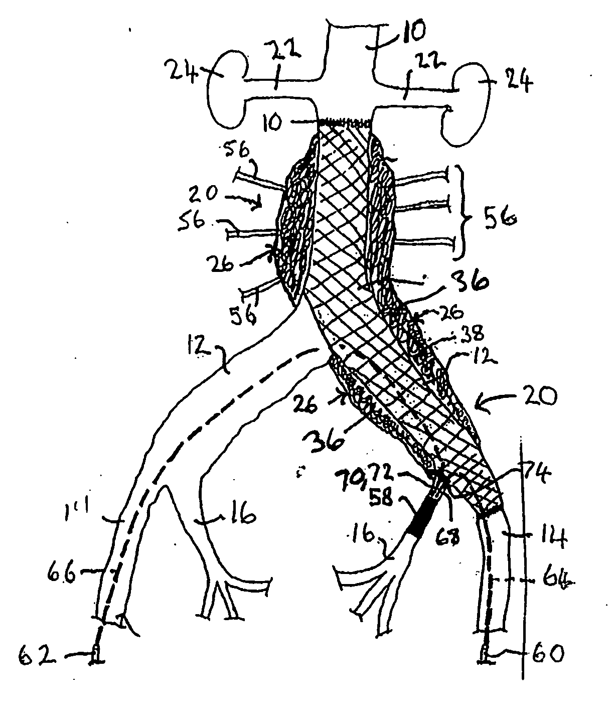
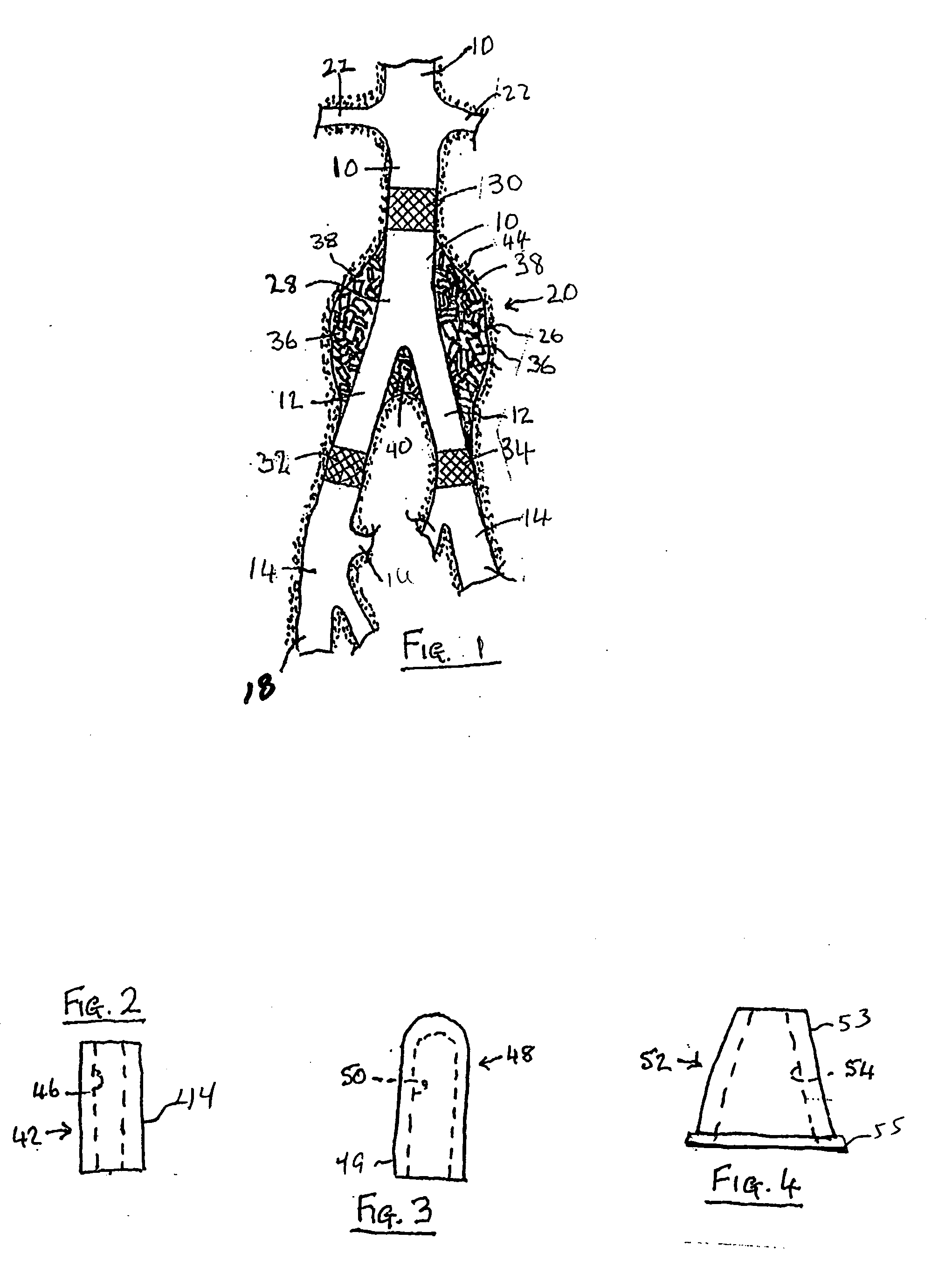
[0137] For treatment of vascular malformations (such as aneurysm sac, endoloeak nexus within the sac and occluding the feeder vessels), it is an advantage of the invention that the implantable elastomeric matrix elements can be effectively employed without any need to closely conform to the configuration of the vascular malformation, which may often be complex and difficult to model. Thus, in one embodiment, the implantable elastomeric matrix elements of the invention have significantly different and simpler configurations.
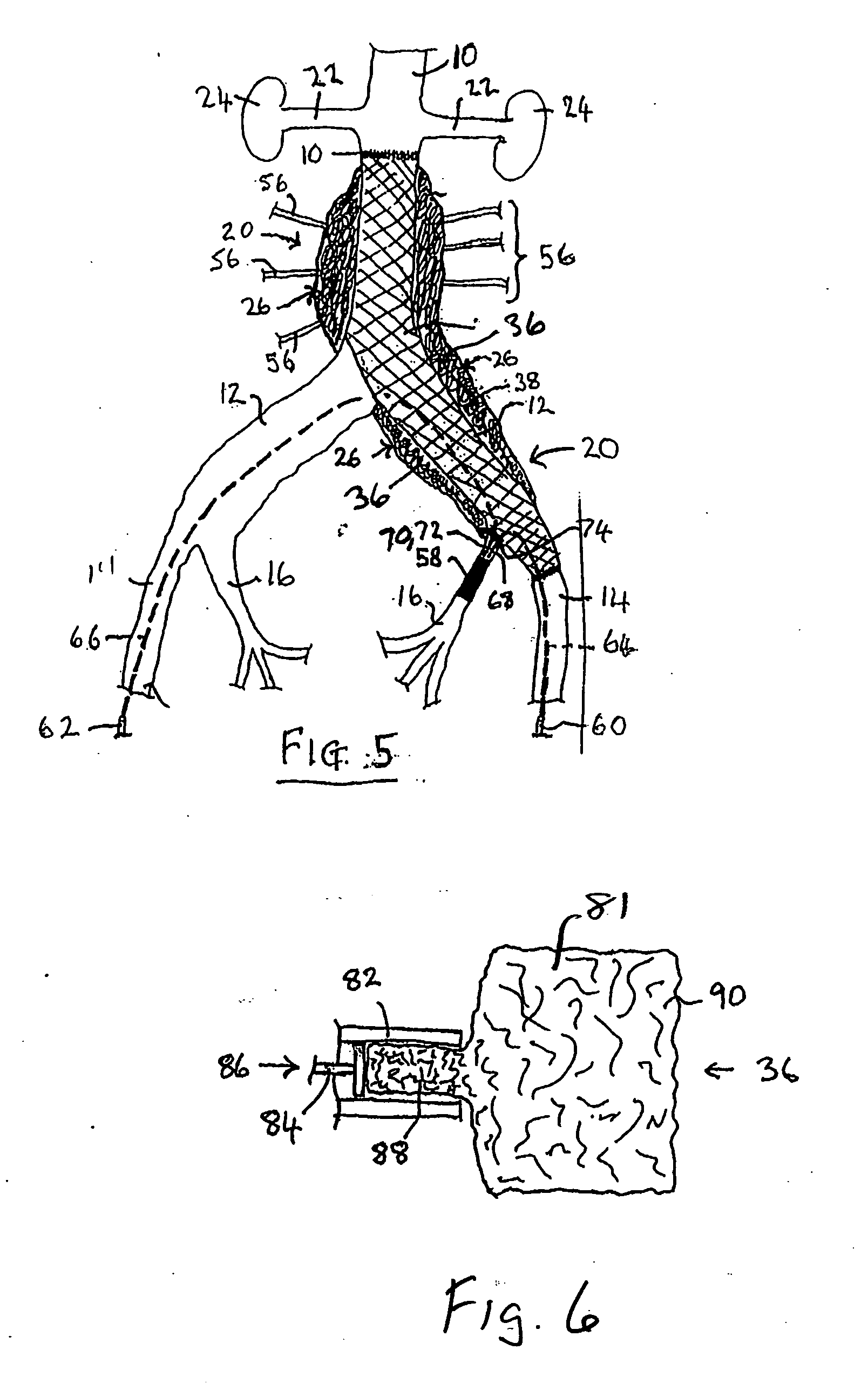
[0138] The selection of suitable implants for inclusion in a group of implants to be delivered into a target cavity may be made on the basis of imaging, personal observation by the medical practitioner, or by other diagnostic methods such as CT scans. The selection may be determined or adjusted during an implant delivery procedure according to the number of implants 36 that can be accommodated or preferably to substantially pack or fill the target vascular site, such as aneurysm volume 38, or by other factors that become apparent or develop during the procedure. Thus, the surgeon or other practitioner may increase or decrease the number of implants to be delivered or use a different size of implant. In this, and other, ways the invention provides a flexible system for the treatment of vascular irregularities. The invention is not limited to a mechanical implementation of procedures devised in response to diagnostic conclusions based upon somatic conditions existing at a point in time prior to the moment of implant delivery but can permit the observations and judgments of the surgeon to be implemented in “real time.”
[0139] One broad aspect of the invention comprises a method for the treatment of late, or post-operative endoleaks that are identified after an endograft has been implanted. The existence of such late endoleaks can be identified in post-operative computerized tomography, “CT” scans that can be or are generally performed at regular intervals following an endograft procedure. Pursuant to the present invention, one method of treating late endoleaks comprises the introduction of an occupying body of individual, shaped implants into the aneurysm sac. The occupying body of implants can be selected to occupy a substantial proportion of the aneurysm sac in the perigraft space and to reduce blood flow or reduce the amplitude of hemodynamic forces acting on the aneurysm or other vascular wall.
[0140] These self-expandable conformal implants are machined from a block of biodurable elastomeric reticulated matrix using custom dies. The implants are preferably cylindrical in shape and may be tapered at one or both ends to allow the implants to be more easily loaded into the delivery catheters owing to ease of compressing the tapered ends to facilitate their entry or matching or mating with the delivery catheters, syringe, etc. Implants with flat non-tapered ends or slightly curved non-tapered ends can be somewhat difficult and challenging to compress and load into delivery catheters due to the difficulty in compressing larger cross-sections into small diameters or for entry or matching or mating with the small diameter delivery catheters, syringes, etc. In another embodiment, the VOD configuration, with no cuts, slots, or other irregularities, is designed to promote continuous contact with the vessel wall along the longitudinal length of the implant to minimize or prevent migration. Also, implants having cylindrical configurations at least partially, at times can facilitate machining.
[0141] Another embodiment of this invention, then, involves the use of a metallic frame to which a sufficient amount of reticulated elastomeric material is attached. The purpose of using a metallic frame to “house” the polymeric material is to minimize the amount of material required for occlusion, thereby offering a lower profile implant for compression into a suitable delivery catheter. It is also the purpose of the metallic frame to impart radiopacity to the implant. In this embodiment, instead of delivering an oversized polymeric implant which would be necessary to resist blood flow, a metallic frame enables the implant to be sized to the exact diameter and dimensions of the target vessel. The metallic frame may be in the form of a tubular structure similar to a stent, a helical or coil-like structure, an umbrella structure, or other structure generally known to those skilled in the art. The frame is preferably comprised of metals which have shape memory, including, but not limited to, nitinol. Attachment of the elastomeric material can be accomplished by means including, but not limited to, chemical bonding or adhesion, suturing, pressure fitting, compression fitting, and other physical methods.
[0142] Another aspect of this invention comprises enhanced implants that are reinforced with internal metallic support structures. These internal support structures are intended to ensure that the implant is properly placed and oriented within the vessel, that is, oriented longitundinally such that the central axis of the cylindrical implant is aligned in a parallel direction to the flow of the blood through the vessel. It is also the purpose of these internal metallic support structures to impart radiopacity to the implant. The internal support structure is embedded into the foam implant and may be in the form of a straight or curved wire, helical or coil-like structure, umbrella structure, or other structure generally known to those skilled in the art. The internal support structure is preferably comprised of metals with shape memory including, but not limited to, platinum and nitinol. Embedding of the support structure would be done subsequent to machining of the foam implant, and would be secured within the implant such that natural systolic forces experienced in the vasculature cannot dislodge or otherwise displace the structure.

Problems solved by technology

When an aortic aneurysm bursts, the patient bleeds into the internal body cavity and the event is usually fatal within minutes.
Moreover, the odds of surviving emergency surgery to repair a ruptured aneurysm are low; only 50% of patients survive an emergency repair procedure.
A problem occurring with many endovascular grafts is that of residual flow into the perigraft space between the endograft and the aneurysmal vessel wall, a complication commonly referred to as an “endoleak”.
The persistence of pressure and / or reintroduction of pressure on the aneurysm walls can place the patient at continued risk of rupture, particularly when the endoleak is accompanied by an increase in aneurysm size.
Type I endoleaks are device-related leaks that result from a failure to adequately seal the attachment sites of the endograft to the vessel walls.
Previously there was no satisfactory treatment approach to combat Type I or Type II endoleaks.
The art lacks a fully satisfactory and effective approach to treatment of endoleaks, and applicants are not aware of any acceptable device approved by the U.S. Food and Drug Administration (“FDA”) to address this problem.
However, this approach has not been effective in resolving or treating endoleaks on a consistent basis.
The treatment of any type of vascular malformation such as endoleaks or aneurysm space is very challenging owing to difficulty in accessing the target space especially in the presence of existing endografts or endografts placed in the aneurysm sac during the surgery.
In addition, the difficulty in delivering large devices, preferably in a compressed state and pushed through the entire length of the delivery catheters, raises issues and challenges that have not been addressed by prior art or existing devices.
Known secondary procedures to seal off endoleaks are technically demanding and are not always successful in creating a durable exclusion of perigraft flow.
Transarterial embolization of feeding and draining vessels is a technically demanding and time-consuming procedure, and it does not always lead to complete endoleak occlusion, as new collateral vessels often emerge and continue to perfuse the sac.
Direct puncture and injection of thrombin and / or coils into the sac is also a less-than-ideal solution, due to the significant risks of embolization through the draining vessels, the costs associated with use of large numbers of platinum coils, and the difficulty of targeted positioning of one or more coils at the endoleak nexus within the sac.
Several methods have been proposed for addressing the problem of endoleaks, but they all have certain drawbacks and none is entirely satisfactory and effective for treating or preventing endoleaks.
There are several difficult challenges and issues associated with procedures, methods and delivery methods for satisfactory and effective for treatment or prevention of endoleaks and the current procedures do not fully appreciate the complexities and difficulties associated with accessing the vascular malfunction sites surrounding the endografts.
Most contemporary vascular occlusion devices, such as coils, thrombin, glue, GELFOAM, PVA articles, alcohol injections, etc., have serious limitations or drawbacks, including, but not limited to, early or late recanalization, incorrect placement or positioning, and migration.
Also, some of the devices are physiologically unacceptable and engender unacceptable foreign body reactions or rejection.

Method used


Image

  • Endovascular treatment devices and methods
  • Endovascular treatment devices and methods
  • Endovascular treatment devices and methods

Examples


example 1

Fabrication of a Crosslinked Reticulated Polyurethane Matrix

[0208] The aromatic isocyanate RUBINATE 9258 (from Huntsman) was used as the isocyanate component. RUBINATE 9258, which is a liquid at 25° C., contains 4,4′-MDI and 2,4′-MDI and has an isocyanate functionality of about 2.33. A diol, poly(1,6-hexanecarbonate)diol (POLY-CD CD220 from Arch Chemicals) with a molecular weight of about 2,000 Daltons was used as the polyol component and was a solid at 25° C. Distilled water was used as the blowing agent. The blowing catalyst used was the tertiary amine triethylenediamine (33% in dipropylene glycol; DABCO 33LV from Air Products). A silicone-based surfactant was used (TEGOSTAB® BF 2370 from Goldschmidt). A cell-opener was used (ORTEGOL® 501 from Goldschmidt). The viscosity modifier propylene carbonate (from Sigma-Aldrich) was present to reduce the viscosity. The proportions of the components that were used are set forth in the following table:

TABLE 1IngredientParts by WeightPolyo...

example 2

Reticulation of a Crosslinked Polyurethane Foam

[0216] Reticulation of the foam described in Example 1 was carried out by the following procedure: A block of foam measuring approximately 15.25 cm×15.25 cm×7.6 cm (6 in.×6 in.×3 in.) was placed into a pressure chamber, the doors of the chamber were closed, and an airtight seal to the surrounding atmosphere was maintained. The pressure within the chamber was reduced to below about 100 millitorr by evacuation for at least about two minutes to remove substantially all of the air in the foam. A mixture of hydrogen and oxygen gas, present at a ratio sufficient to support combustion, was charged into the chamber over a period of at least about three minutes. The gas in the chamber was then ignited by a spark plug. The ignition exploded the gas mixture within the foam. The explosion was believed to have at least partially removed many of the cell walls between adjoining pores, thereby forming a reticulated elastomeric matrix structure.

[0217...

example 3

Fabrication of a Crosslinked Polyurethane Matrix

[0224] The isocyanate component was RUBINATE 9258, as described in Example 1. A polyol comprising 1,6-hexamethylene polycarbonate (Desmophen LS 2391, Bayer Polymers), i.e., a diol, with a molecular weight of about 2,000 Daltons was used as the polyol component and was a solid at 25° C. Distilled water was used as the blowing agent. The blowing catalyst, surfactant, cell-opener and viscosity modifier of Example 1 were used. The proportions of the components that were used is set forth in the following table:

TABLE 3IngredientParts by WeightPolyol Component150Viscosity Modifier8.72Surfactant3.33Cell Opener0.77Isocyanate Component81.09Isocyanate Index1.00Distilled Water4.23Blowing Catalyst0.67

[0225] The polyol component was liquefied at 70° C. in a circulating-air oven, and 150 g thereof was weighed out into a polyethylene cup. 8.7 g of viscosity modifier was added to the polyol component to reduce the viscosity and the ingredients were...


PUM

PropertyMeasurementUnit
Fractionaaaaaaaaaa
Fractionaaaaaaaaaa
Diameteraaaaaaaaaa

Abstract

A device for treating or preventing a vascular condition at a mammalian vascular site, comprises an implant formed from a compressible, reticulated elastomeric matrix in a shape conducive to delivery through a delivery instrument. One or more implants are delivered in a compressed state to the mammmalian vascular site where each implant recovers substantially to its uncompressed state following deployment from a delivery instrument. In a preferred embodiment the matrix comprises cross-linked polycarbonate polyurethane-urea or cross-linked polycarbonate polyurea-urethane. In another preferred embodiment the matrix comprises a cross-linked polycarbonate polyurethane. In a yet further embodiment, the matrix comprises thermoplastic polycarbonate polyurethane or thermoplastic polycarbonate polyurethane-urea.

Description

CROSS-REFERENCE TO RELATED APPLICATION [0001] This application is based upon co-pending, commonly assigned, U.S. provisional patent application Ser. No. 60 / 538,597, filed Jan. 23, 2004, incorporated herein by reference.FIELD OF THE INVENTION [0002] The present invention relates to endovascular treatment devices and methods useful for treatment of vascular conditions such as vascular aneurysms and other vascular abnormalities, defects or malformations. In particular, although not exclusively, the invention relates to devices and methods useful in conjunction with grafts or graft implantation procedures, for example, aneurysm endografts and aneurysm endograft implantation procedures, which devices and methods are helpful in providing management of leakage commonly associated with such endografts. BACKGROUND OF THE INVENTION [0003] An abdominal aortic aneurysm (hereinafter “AAA”) is a common clinical problem which occurs when the walls of the descending aorta weaken and bulge into a sa...

Claims


Application Information

Patent Timeline
IPC IPC(8): A61B17/12A61F2/20A61L31/06
CPCA61B17/12022A61B17/12118A61B17/12181A61B2017/1205A61L31/06C08L75/04
Inventor JORDAN, MAYBELLEDATTA, ARINDAMFRIEDMAN, CRAIG F.SANDERSON, GEORGEKULA, JOHN
Owner THE BIOMERIX CORP
Learn More