
Device specific finite element models for simulating endovascular treatment

a medical device and finite element model technology, applied in the field of medical device deployment simulation, can solve the problems of severe headache, nausea, vomiting and/or loss of consciousness, and endovascular treatment carry risks, and carry significant risks

Active Publication Date: 2015-08-20
MAYO FOUND FOR MEDICAL EDUCATION & RES +1
View PDF0 Cites 10 Cited by
  • Summary
  • Abstract
  • Description
  • Claims
  • Application Information

AI Technical Summary

Benefits of technology

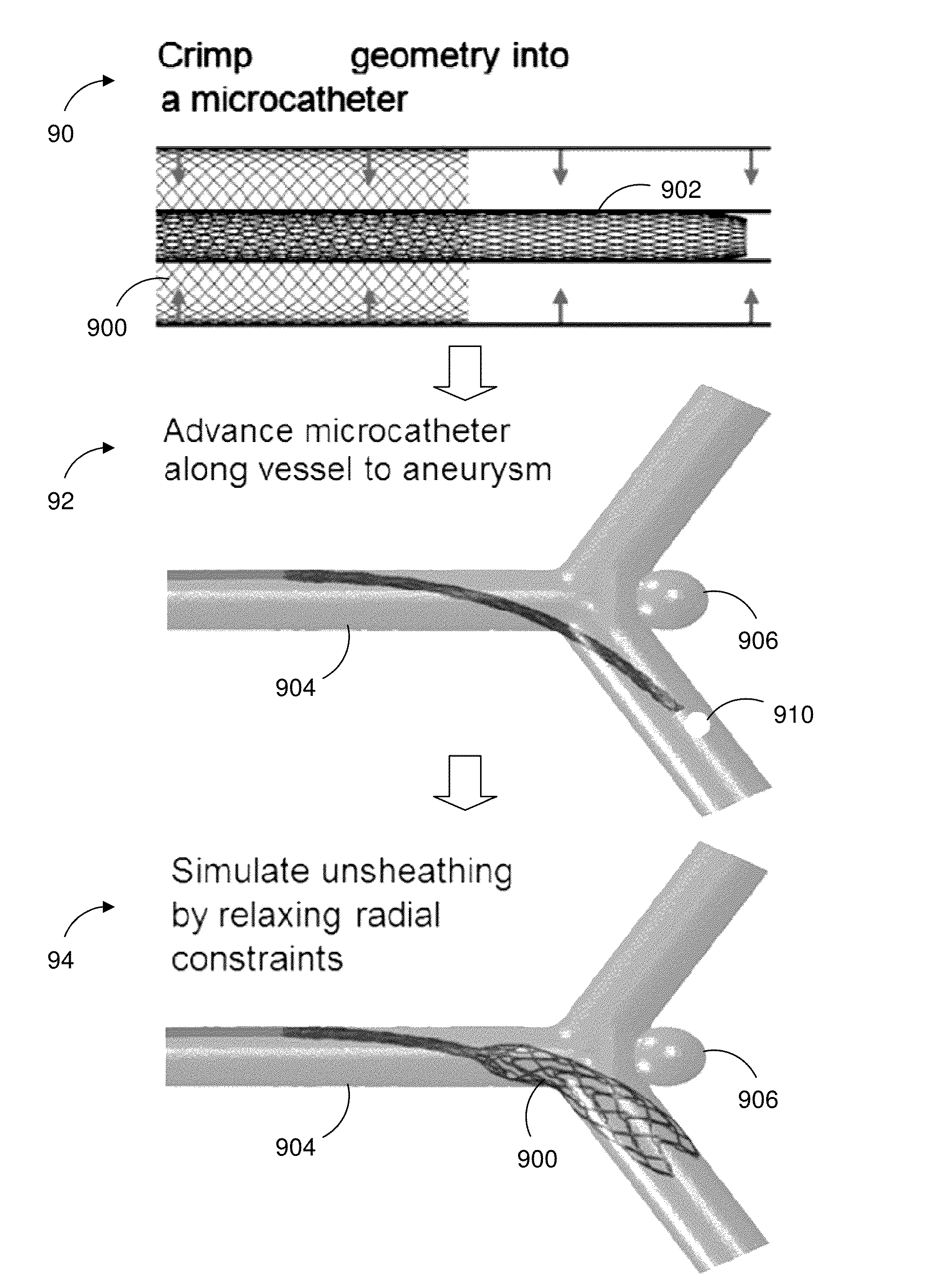
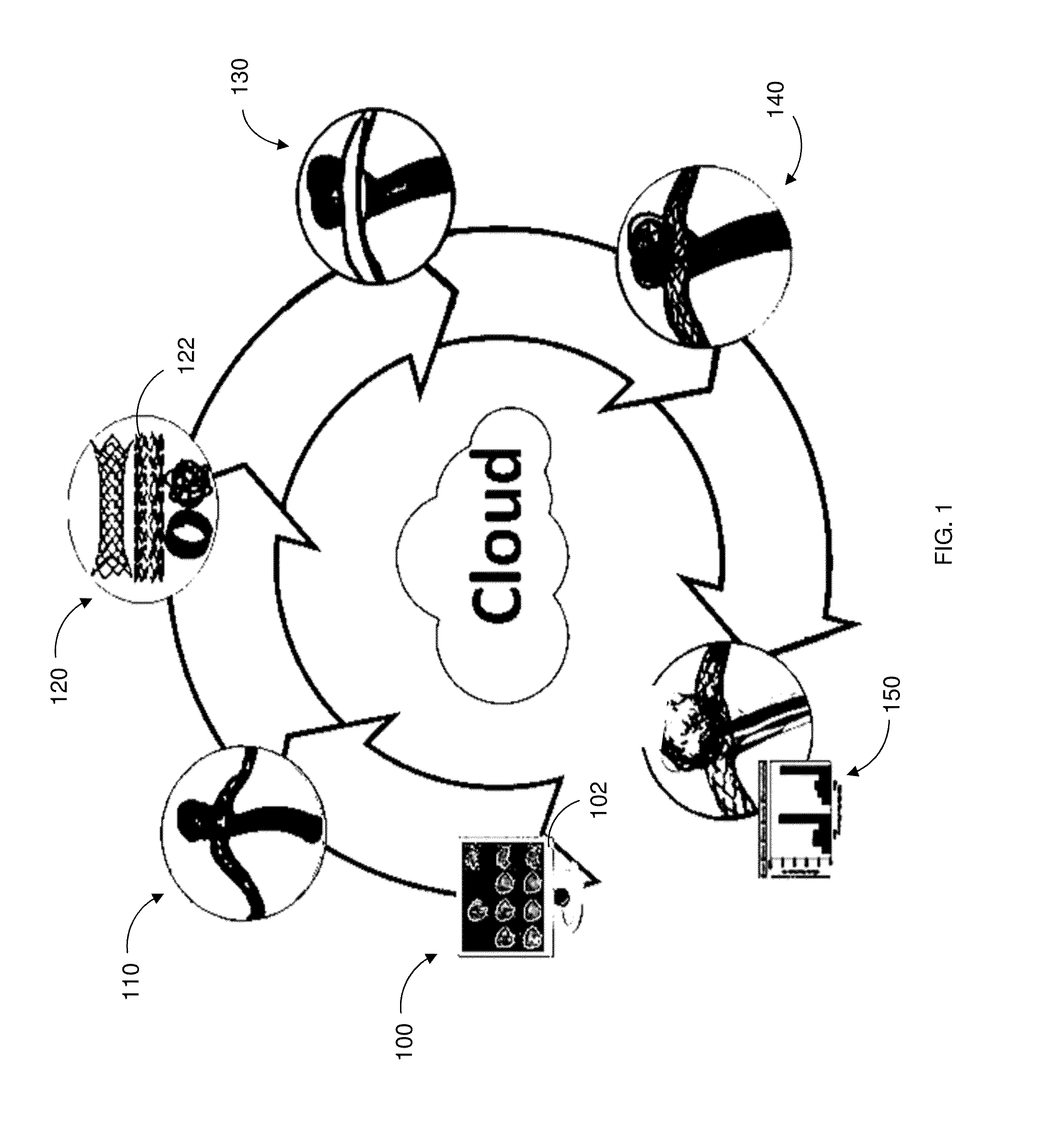
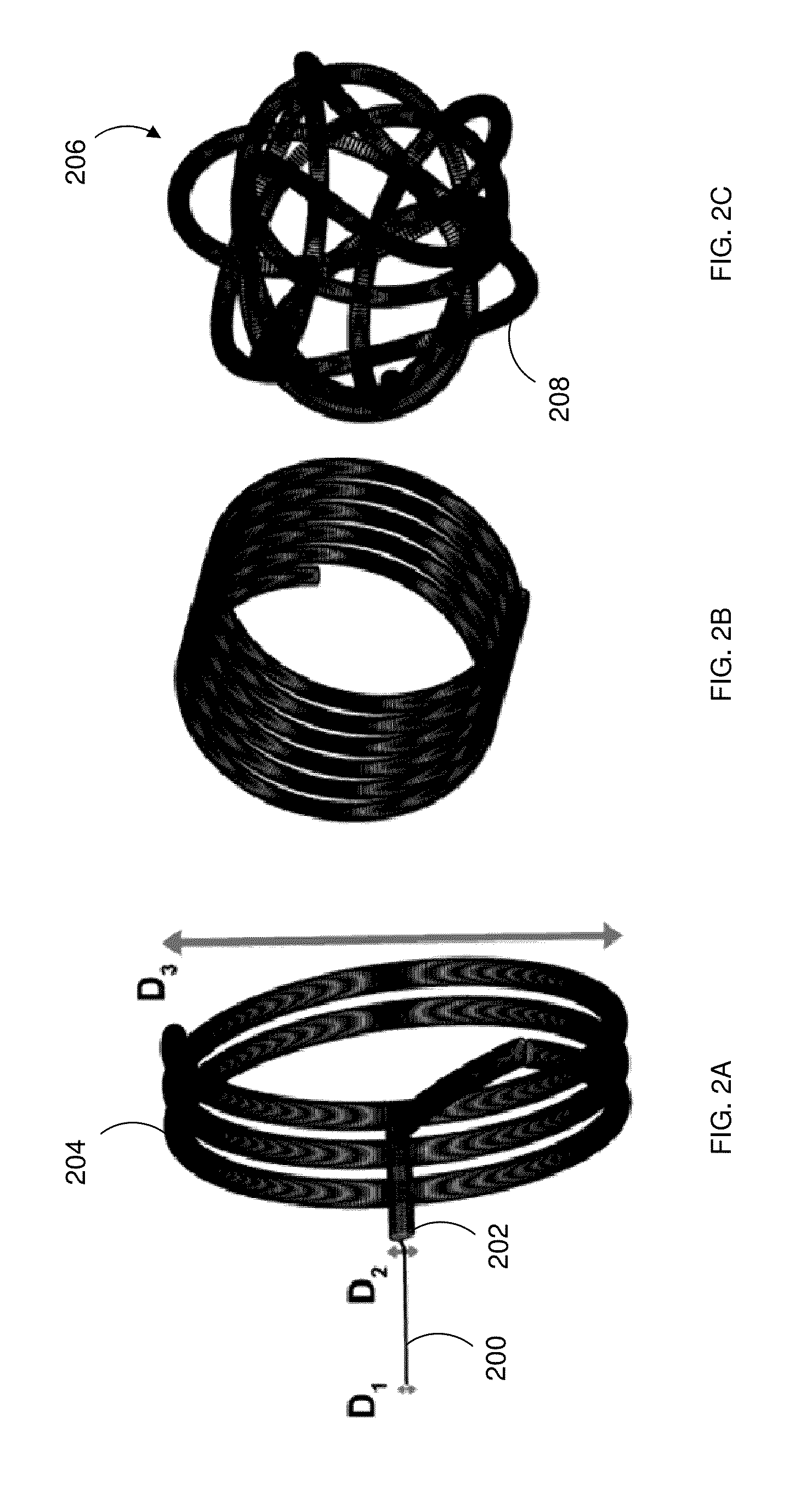
The present invention provides a system and method for simulating the deployment and hemodynamic outcomes of medical devices used in the treatment of cardiovascular diseases. The system includes a computer cluster and a database of medical device models constructed using finite element analysis and three dimensional beam analysis. The method involves receiving patient clinical data and using it to virtually construct an anatomical structure model of the patient. The system can then simulate the deployment of various medical devices in the anatomical structure model, and the resulting hemodynamic outcomes can be analyzed. The invention provides a more accurate and reliable tool for planning and simulating medical device dynamics, which can help improve the efficacy and safety of these procedures.

Problems solved by technology

Larger aneurysms may cause severe headaches, nausea, vision impairment, vomiting and / or loss of consciousness.
This procedure is currently done open, in the form of a craniotomy (i.e., cutting into the skull to access the brain), which carries with it significant risks.
Unfortunately, endovascular treatments carry risks.
These tools, however, construct a simplistic medical device model, ignore or simplify fluid dynamic simulations, do not construct an anatomical model from the patient's image data, and use a haptic device, which ultimately presents an unrealistic and unreliable post-treatment fluid dynamic prediction.

Method used


Image

  • Device specific finite element models for simulating endovascular treatment
  • Device specific finite element models for simulating endovascular treatment
  • Device specific finite element models for simulating endovascular treatment

Examples


Embodiment Construction

,” one will understand how the features of this invention provide several advantages over current designs.

[0015]An aspect of the present disclosure provides a system for simulating medical device dynamics. The system includes a database configured to store medical device models and one or more processors. The one or more processors are configured to virtually construct an anatomical structure model of a patient, simulate a deployment of a plurality of the medical device models in the anatomical structure model, and simulate hemodynamic outcomes of the deployment of the plurality of the medical device models in the anatomical structure model.

[0016]Another aspect of the present disclosure provides a method for simulating medical device dynamics. The method includes storing a computer readable database comprising medical device models, constructing, by the one or more processors, an anatomical structure model based on patient clinical data, simulating a deployment of a plurality of the...


PUM


Abstract

Systems and methods provide a novel computational approach to planning the endovascular treatment of cardiovascular diseases. In particular, the invention simulates medical device deployment and hemodynamic outcomes using a virtual patient-specific anatomical model of the area to be treated, high-fidelity finite element medical device models and computational fluid dynamics (CFD). In an embodiment, the described approach investigates the effects of coil packing density, coil shape, aneurysmal neck size and parent vessel flow rate on aneurysmal hemodynamics. A processor may receive patient clinical data used to construct the relevant anatomical structure model. The processor may access medical device models constructed using finite element analysis and three dimensional beam analysis, and simulates the deployment of selected medical devices in the anatomical structure model. The selected medical device models and the anatomical structure model mesh, allowing the processor to simulate hemodynamic outcomes using computational fluid dynamics.

Description

CROSS-REFERENCES TO RELATED APPLICATIONS[0001]This application is a continuation of U.S. patent application Ser. No. 14 / 285,265, filed May 22, 2014, entitled “DEVICE SPECIFIC FINITE ELEMENT MODELS FOR SIMULATING ENDOVASCULAR TREATMENT,” which is a continuation-in-part of U.S. patent application Ser. No. 14 / 165,061, filed Jan. 27, 2014, entitled “DEVICE SPECIFIC FINITE ELEMENT MODELS FOR SIMULATING ENDOVASCULAR TREATMENT.” All of these applications are incorporated by reference in their entireties. Furthermore, any and all priority claims identified in the Application Data Sheet, or any correction thereto, are hereby incorporated by reference under 37 C.F.R. §1.57.STATEMENT REGARDING FEDERALLY SPONSORED RESEARCH[0002]This invention was made with government support under Grant No. 1151232 awarded by the National Science Foundation. The U.S. government has certain rights in the invention.BACKGROUND[0003]1. Field[0004]The present invention is generally related to medical device deployme...

Claims


Application Information

Patent Timeline
Patent Type & Authority Applications(United States)
IPC IPC(8): G09B23/28
CPCG09B23/28G09B5/02
Inventor BABIKER, MOHAMED HAITHEMFRAKES, DAVID H.CHONG, BRIAN W.
Owner MAYO FOUND FOR MEDICAL EDUCATION & RES
Learn More