
Compound netty stent

A technology of inner stent and support frame, which is applied in the field of medical devices, can solve the problems of unfavorable graft delivery, narrow diameter, impossibility, etc., and achieve the effect of ensuring long-term unobstructed and easy delivery

Inactive Publication Date: 2012-07-11
曲乐丰 +1
View PDF2 Cites 10 Cited by
  • Summary
  • Abstract
  • Description
  • Claims
  • Application Information

AI Technical Summary

Problems solved by technology

Its disadvantage is that when the shape or location of the lesion is not suitable for endovascular exclusion, such as the proximal end of the aneurysm or the dissection opening is adjacent to important blood vessel branches, the neck of the aneurysm is too short to provide enough space for the proximal end of the graft. Anchoring, or when the lesion involves extensive thoracoabdominal aorta, or when aortic dissection involves important branch vessels such as the brachiocephalic trunk, left common carotid artery, left subclavian artery, and celiac trunk, the graft should be placed in the isolated tumor body At the same time, it will also obscure these branch vessels, resulting in serious consequences
The disadvantages of this kind of stent are: firstly, the multilayer metal hard stent has a large volume after shrinkage and needs to be assembled in a guide sheath with a large diameter, which is not conducive to the delivery of the graft; secondly, when this kind of graft is used in tube Multi-layer hard stents will make the diameter of the vessel narrower
Finally, once the stent mesh at the branch vessel is blocked in the long-term, due to the characteristics of its own metal hard stent, it will become impossible to recanalize the vascular intervention at the branch entrance, and an intervascular intervention has to be performed. open surgery

Method used


Image

  • Compound netty stent
  • Compound netty stent
  • Compound netty stent

Examples


Embodiment 1

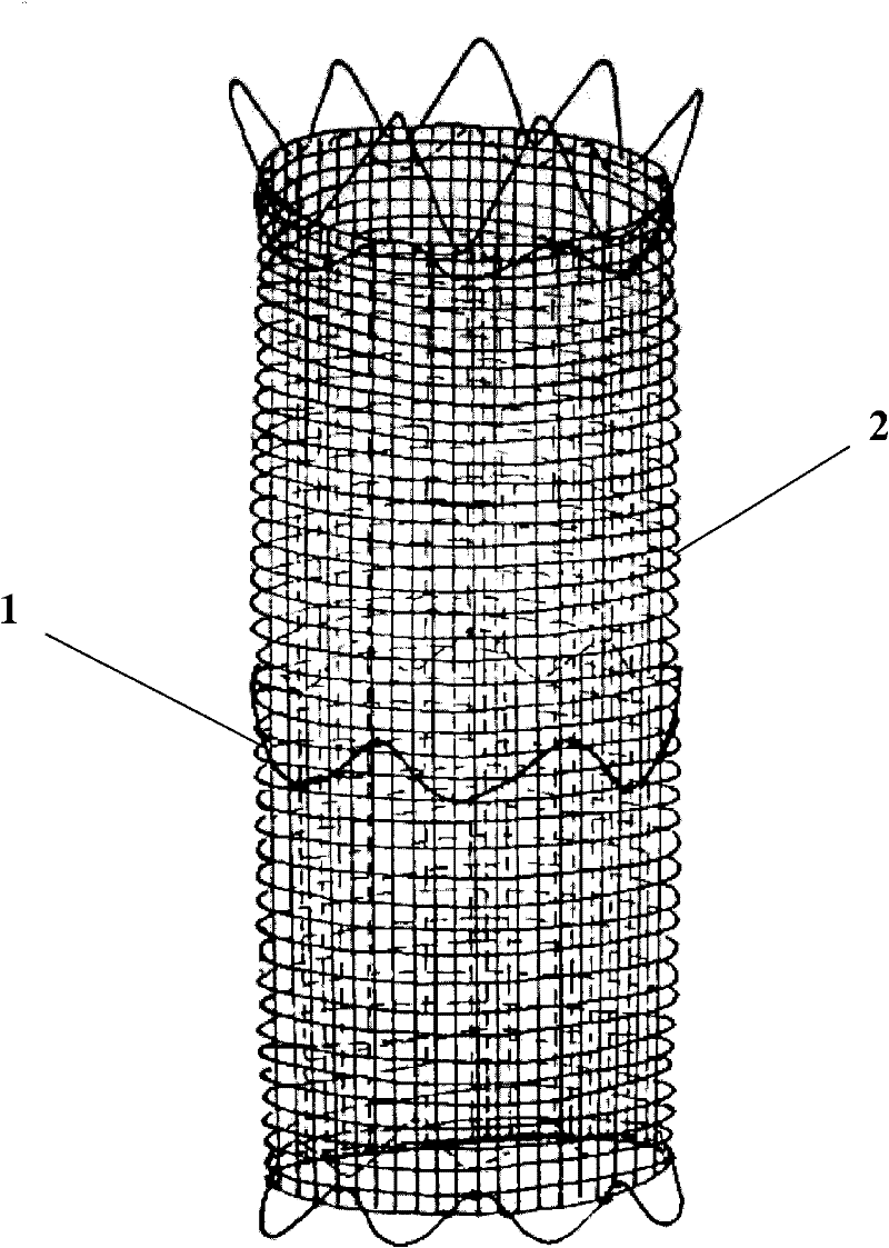
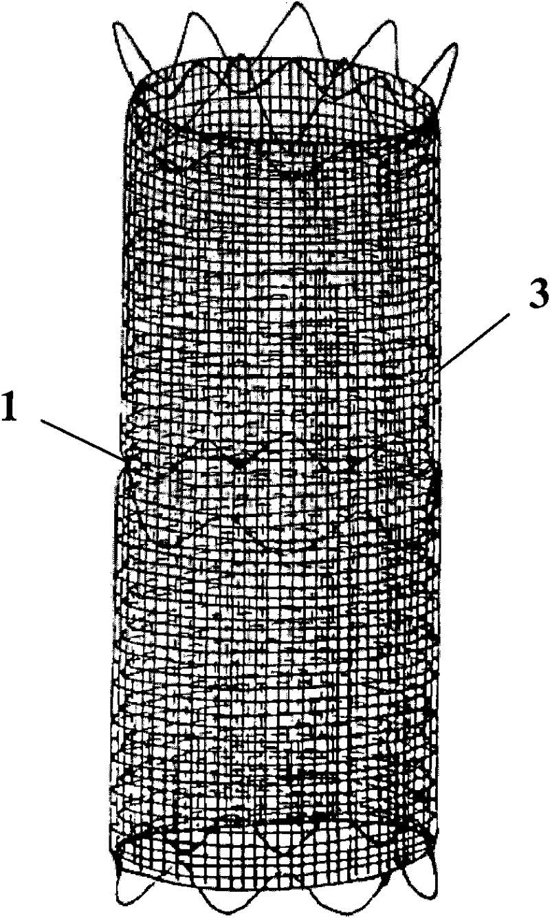
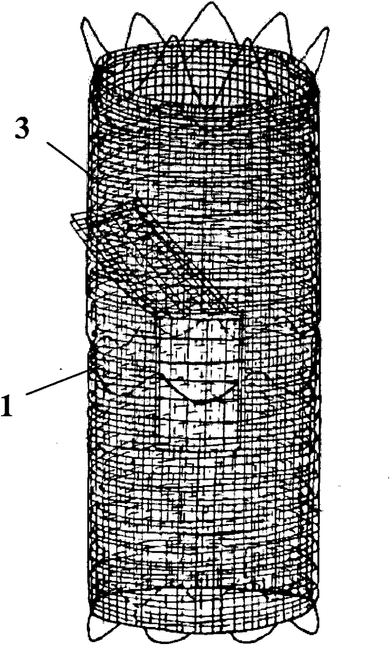
[0043] Composite mesh support, see attached Figure 1-4 .

[0044] It consists of a plurality of Z-shaped elastic metal support frames arranged axially at certain intervals to form a cylindrical elastic support frame and a three-dimensional flow-limiting net formed by overlapping and compounding single-layer gauze or multi-layer gauze. The gauze net is woven into a soft net with dense mesh distribution from flexible thin wire material. figure 1 It is a net-like support composed of a single-layer gauze 2 covering the inner side of the support frame 1, figure 2 The three-dimensional current-limiting net 3 formed by overlapping multiple layers of gauze is covered on the outside of the support frame 1 to form a composite mesh support, and image 3 What is shown is that the innermost layer of the three-dimensional flow-limiting net 3 is covered on the inner wall of the bracket, and the remaining layers are covered on the outer wall of the bracket, forming a sandwich sandwich struc...

Embodiment 2

[0046] Folding three-dimensional net bracket, see attached Figure 5a , 5b , 5c and 5d.

[0047] On the basis of Example 1, the three-dimensional current-limiting net formed by overlapping and compounding the multi-layer gauze is changed to a folded three-dimensional current-limiting net with a multi-layer structure formed by folding the single-layer gauze 2 back and forth multiple times. The direction is circumferential as Figure 5a or axial as Figure 5b , this embodiment takes two times of folding as an example to form a 3-layer mesh structure. After stretching the folded three-dimensional flow-limiting net into a rectangular single-layer gauze, set the horizontal side as wide and the vertical side as long, then as Figure 5a The width of the single-layer gauze net is 3 times of the circumference of the circular cross section when it is folded in the circumferential direction, and the length is equal to the longitudinal length of the mesh support of the mesh support. ...

Embodiment 3

[0050] Axially crimped three-dimensional current limiting mesh bracket, see attached Figure 6a , 6b .

[0051] On the basis of Example 1, the three-dimensional current-limiting net formed by overlapping and compounding multi-layer gauze is changed to a single-layer gauze 2, and the axial center of the cylindrical support is concentrically multi-circled to form a multi-layer curled three-dimensional current limiting Net such as Figure 6a shown. The length of the single-layer gauze is an integer multiple of the perimeter of the cross-section of the support frame, twice as long as it is curled around the support frame for 2 turns, and the width is equal to the longitudinal length of the mesh support. After the crimping is completed, the free starting edge and the terminal edge are sutured on the respective contacting mesh surfaces to form a closed cylindrical three-dimensional current-limiting mesh, and each layer of mesh is interspersed and connected with tenacious sutures ...


PUM


Abstract

The invention relates to a netty stent for endovascular treatment. An existing technical scheme for treating vascular dilation diseases by the aid of a netty stent includes that a plurality of netty metal stents are coaxially overlapped and metal thin wires are woven three-dimensionally, so that a three-dimensional netty stent is formed, the principle includes that the disorder state of blood in a dilated blood vessel cavity is changed by the netty stent, and lesions are promoted to be repaired by a natural blood coagulation mechanism. The technical scheme of the invention includes that on the basis of an existing vascular laminating film stent consisting of an elastic supporting frame and a laminating film, a flow limiting screen with a flexible three-dimensional structure is used for replacing the laminating film, and the supporting frame and the flow limiting screen are compounded internally and externally so as be connected integrally. The compound netty stent further can be manufactured into a separate combined type or integral branch stent. The compound netty stent has the advantages that the compound netty stent is easy in manufacture and flexible in implantation, and an anatomy channel of a lesion blood vessel can be recovered.

Description

technical field [0001] The invention relates to a medical device, more specifically, to a mesh support for intravascular treatment. Background technique [0002] In recent years, with the continuous development of endovascular treatment technology, various types of stent grafts have been widely used. The main structure is a foldable channel composed of a metal support frame and an artificial vascular membrane covering its inner or outer wall. The treatment principle is to use the pipeline structure formed by the stent to isolate the dilated vascular disease and blood flow, so as to avoid the expansion and rupture of the diseased blood vessel and ensure the smooth flow of the blood vessel access. The use of the stent has achieved good results in isolating various aneurysms and arterial dissections to prevent the enlargement and rupture of the aneurysms and dissections. Its disadvantage is that when the shape or location of the lesion is not suitable for endovascular exclusio...

Claims


Application Information

Patent Timeline
IPC IPC(8): A61F2/90A61L27/16
Inventor 曲乐丰张传忠柏骏
Owner 曲乐丰
Learn More