Endovascular treatment sheath having a heat insulative tip and method for using the same

a technology of endovascular treatment and heat insulation, which is applied in the field of medical devices and methods for treating blood vessels, can solve the problems of venous reflux, varicose veins are often painful, and no longer prevent the backflow of blood into superficial veins, so as to prevent the perforation and extravasation of blood vessels

Inactive Publication Date: 2008-08-28
ANGIODYNAMICS INC
View PDF54 Cites 10 Cited by
  • Summary
  • Abstract
  • Description
  • Claims
  • Application Information

AI Technical Summary

Benefits of technology

[0021]The heat insulative tip of the present treatment sheath surrounds and protects the energy emitting face of the optical fiber and prevents the light emitting face from inadvertently contacting the inner wall of the vessel, thereby preventing vessel perforation and extravasation of blood into the perivascular tissue.

Problems solved by technology

When the valves are malfunctioning or only partially functioning, however, they no longer prevent the back-flow of blood into the superficial veins.
Symptoms of reflux include varicose veins and other cosmetic deformities, as well as aching and swelling of the legs.
Aside from being cosmetically undesirable, varicose veins are often painful, especially when standing or walking.
If left untreated, venous reflux may cause severe medical complications such as bleeding, phlebitis, ulcerations, thrombi and lipodermatosclerosis (LDS).
When veins become enlarged, the leaflets of the valves no longer meet properly.
However, while providing temporary relief of symptoms, these techniques do not correct the underlying cause, that is, the faulty valves.
Even with its high clinical success rate, surgical excision is rapidly becoming an outmoded technique due to the high costs of treatment and complication risks from surgery.
The procedure is done on an outpatient basis, but is still relatively expensive due to the length of time required to perform the procedure.
Although a popular treatment option, severe complications can result, such as skin ulceration, anaphylactic reactions and permanent skin staining.
Treatment is limited to veins of a particular size range.
In addition, there is a relatively high recurrence rate due to vessel recanalization.
Current sheath tips are often difficult to clearly visualize under ultrasonic guidance.
The energy reacts with the blood in the vessel and causes the blood to boil, thereby producing hot steam bubbles.
The gas bubbles transfer thermal energy to the vein wall, causing damage to the endothelium and eventual vein collapse.
The exposed optical fiber tip is often damaged during the procedure as it is being withdrawn through the vein.
Blood build up and charring on the energy-emitting face of the fiber tip often results in compromised energy delivery and tip degradation due to intensive heat.
A degraded tip will often break leaving unwanted fragments of the optical fiber tip behind in a patient's body after treatment.
In addition to damage to the exposed laser emitting face of the optical fiber tip, a fiber that extends past the sheath tip may inadvertently come into contact with the vessel wall.
Even unintended and unwanted contact between the optical fiber tip and the inner wall of the vessel can result in vessel perforation and extravasation of blood into the perivascular tissue.
Blood escapes through these perforations into the perivascular tissue, resulting in post-treatment bruising and associated discomfort.
Another problem with currently available sheaths is the difficulty in visualizing the distal end of the exposed fiber, which is very important in correctly positioning the treatment device.
Although the sheath may be designed to be ultrasonically visible, it is often difficult for a physician to know where the tip of the optical fiber is in relation to the edge of the sheath.
Incorrect placement may result in either incomplete occlusion of the vein or non-targeted thermal energy delivery to the deep femoral vein.
Energy that is unintentionally directed into the deep venous system may result in deep vein thrombosis (DVT) and its associated complications including pulmonary embolism (PE).

Method used


Image

  • Endovascular treatment sheath having a heat insulative tip and method for using the same
  • Endovascular treatment sheath having a heat insulative tip and method for using the same
  • Endovascular treatment sheath having a heat insulative tip and method for using the same

Examples


Embodiment Construction

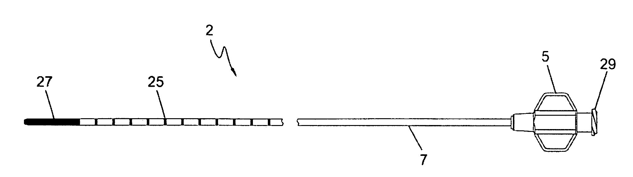
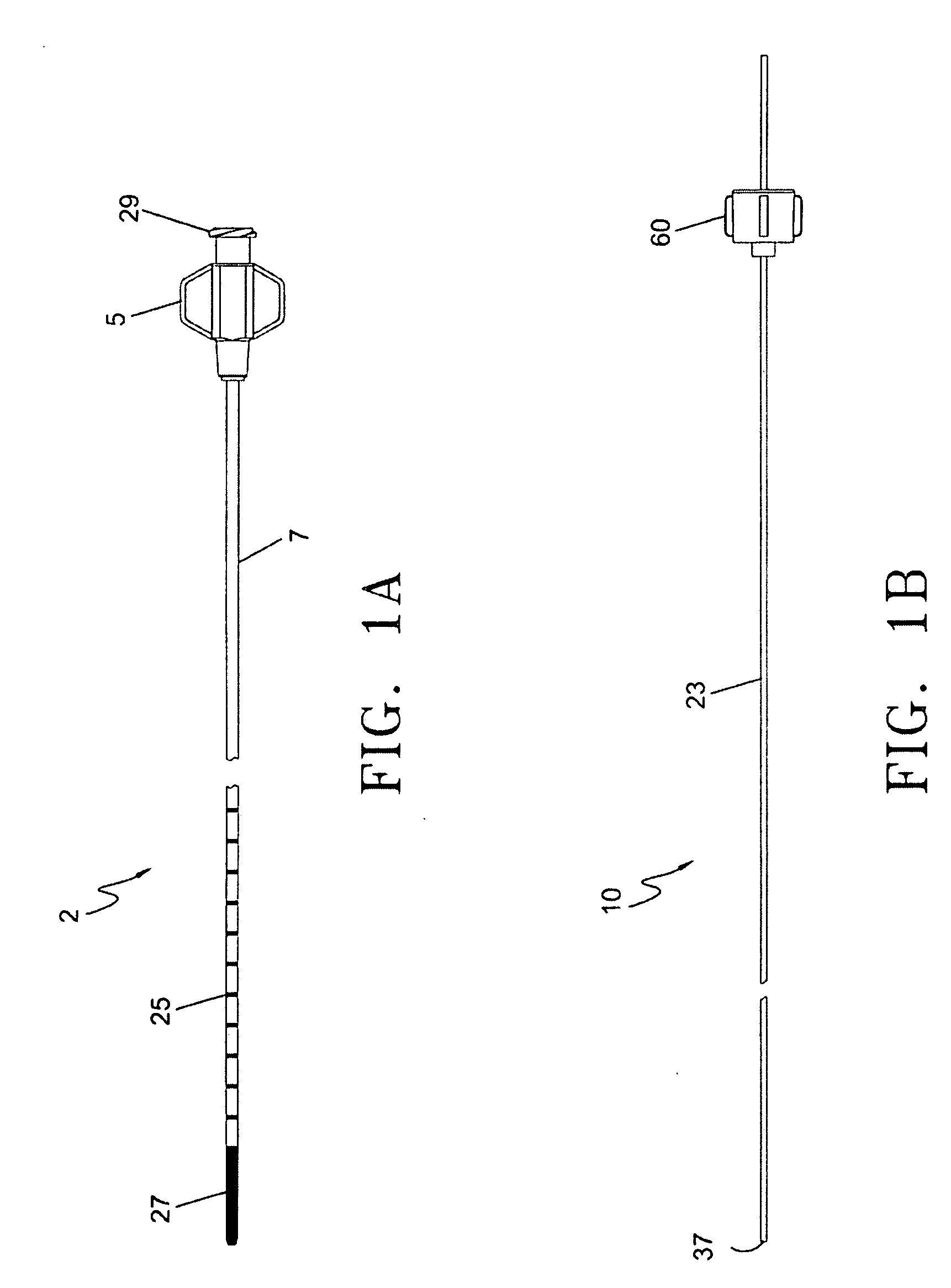
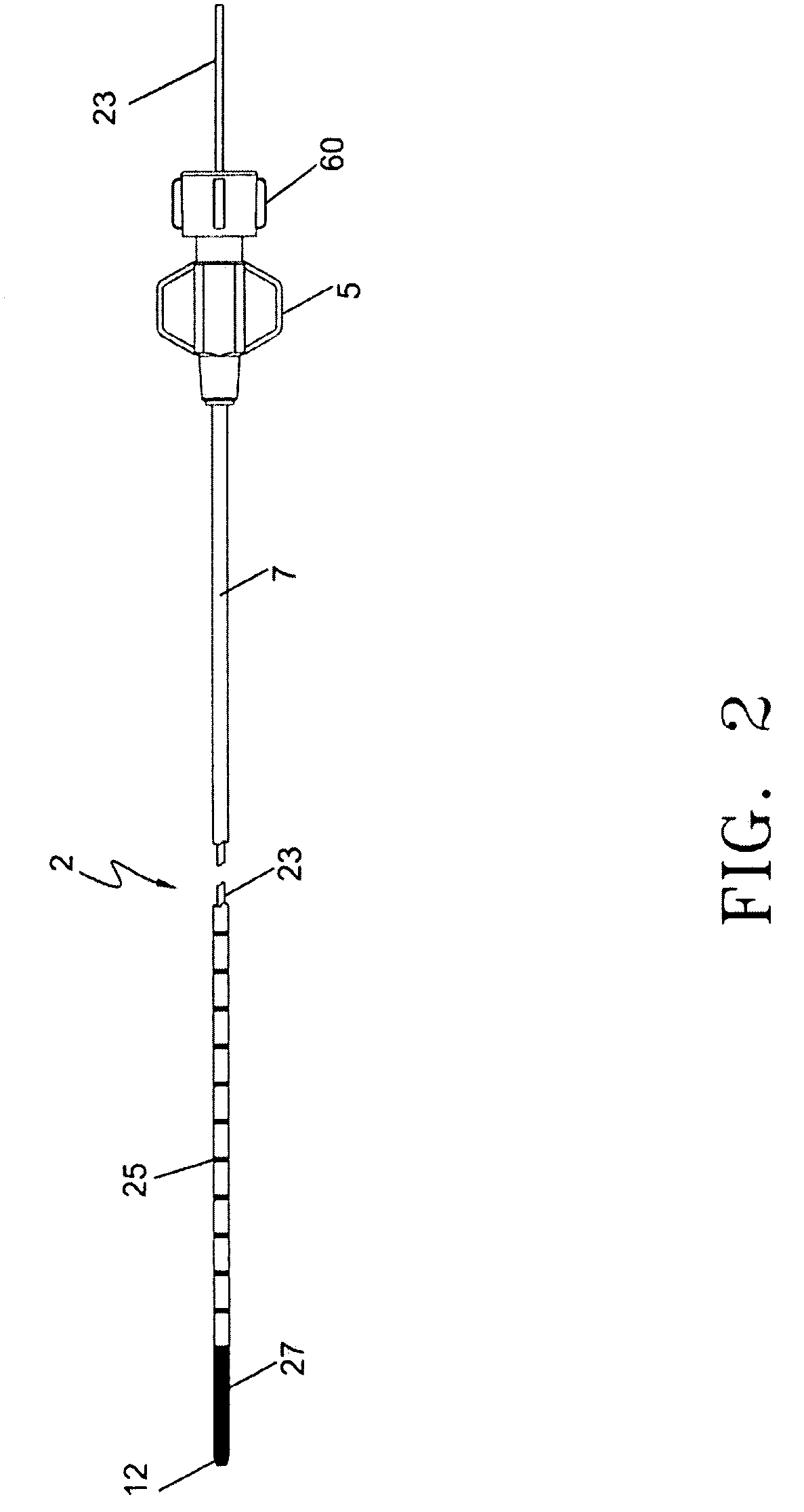
[0032]The present invention is illustrated in FIGS. 1 through 8. A treatment sheath 2 is illustrated in FIG. 1A. The treatment sheath 2 includes a proximal sheath hub 5, a sheath shaft 7 and an insulating tip 27 at the distal end. Extending from the hub 5 to the insulating tip 27 is a through lumen 9 (see FIG. 3). The sheath shaft may optionally include depth / distance markers 25. The sheath shaft 7 may also optionally include a reinforcement metallic element embedded within the polymer shaft 7 such as that disclosed in U.S. patent application Ser. No. 10 / 836,084, which is incorporated herein by reference. The hub 5 includes a standard luer threaded proximal end (treatment sheath connector) 29 for connection to an optical fiber connector 60 (FIG. 1B) or other interventional devices. Hub fittings other than those specifically described herein are within the scope of this invention.

[0033]FIG. 1B illustrates the energy delivery device of the current invention. In particular, the energy ...


PUM


Abstract

A treatment sheath for use with an energy delivery device, such as an optical fiber, is provided with a heat insulative tip. The treatment sheath includes a longitudinal shaft which is designed to receive the optical fiber, and is inserted into a blood vessel to treat diseases such as varicose veins. During treatment, the energy emitting face of the optical fiber is positioned inside the heat insulative tip of the treatment sheath. The heat insulative tip protects the optical fiber emitting face during the delivery of laser energy and prevents the emitting face from inadvertently contacting the inner vessel wall.

Description

CROSS REFERENCE TO RELATED APPLICATIONS[0001]This application is a continuation-in-part of U.S. application Ser. No. 11 / 777,198, filed Jul. 12, 2007, which is a continuation of U.S. application Ser. No. 10 / 613,395, filed Jul. 3, 2003, now U.S. Pat. No. 7,273,478, which claims priority under 35 U.S.C. Section 119(e) to U.S. Provisional Application Ser. No. 60 / 395,218 filed Jul. 10, 2002, all of which are incorporated herein by reference.[0002]This application is also a continuation-in-part of U.S. application Ser. No. 10 / 836,084, filed Apr. 30, 2004, which claims priority under 35 U.S.C. Section 119(e) to U.S. Provisional Application Ser. No. 60 / 516,156 filed Oct. 31, 2003, all of which are incorporated herein by reference.[0003]This application is also a continuation-in-part of U.S. application Ser. No. 11 / 362,239, filed Feb. 24, 2006, which is a continuation of U.S. application Ser. No. 10 / 316,545, filed Dec. 11, 2002, now U.S. Pat. No. 7,033,347, all of which are incorporated here...

Claims


Application Information

Patent Timeline
Patent Type & Authority Applications(United States)
IPC IPC(8): A61B18/22
CPCA61B18/24A61B2019/5425A61B2018/00101A61B2017/22068A61B2090/3925
Inventor CARTIER, WILLIAM A.APPLING, WILLIAM M.
Owner ANGIODYNAMICS INC
Why Eureka
Try Eureka