Thermoplastic interface and shield assembly for separable insulated connector system

a technology of separable insulated connectors and thermal plastics, applied in the direction of coupling protective earth/shielding arrangement, coupling device connection, coupling base/case, etc., can solve the problem of disadvantaged conventional connectors of this typ

Inactive Publication Date: 2009-02-24
COOPER TECH CO
View PDF245 Cites 130 Cited by
  • Summary
  • Abstract
  • Description
  • Claims
  • Application Information

AI Technical Summary

Problems solved by technology

Conventional connectors of this type are disadvantaged in certain aspects and improvements are desired.

Method used


Image

  • Thermoplastic interface and shield assembly for separable insulated connector system
  • Thermoplastic interface and shield assembly for separable insulated connector system
  • Thermoplastic interface and shield assembly for separable insulated connector system

Examples


first embodiment

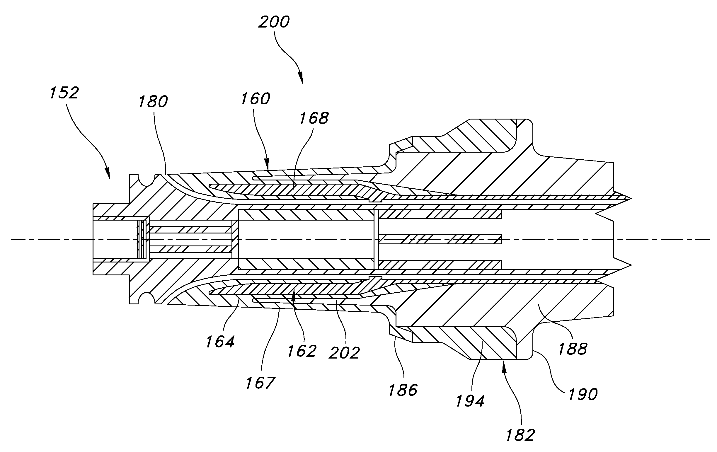
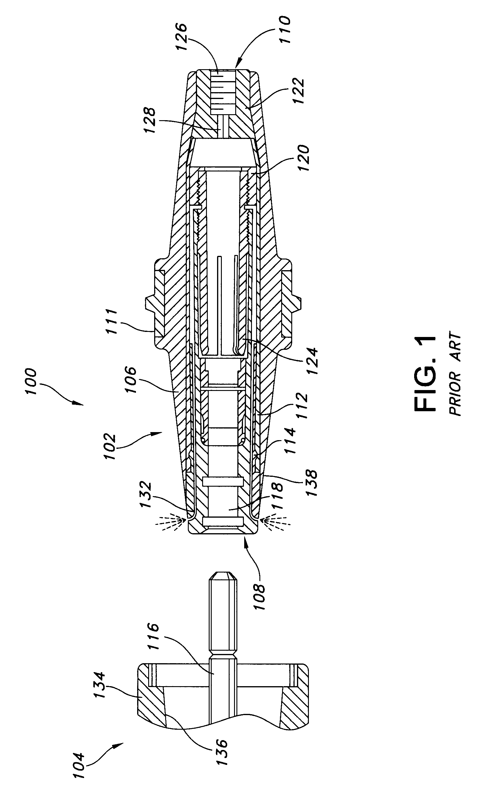
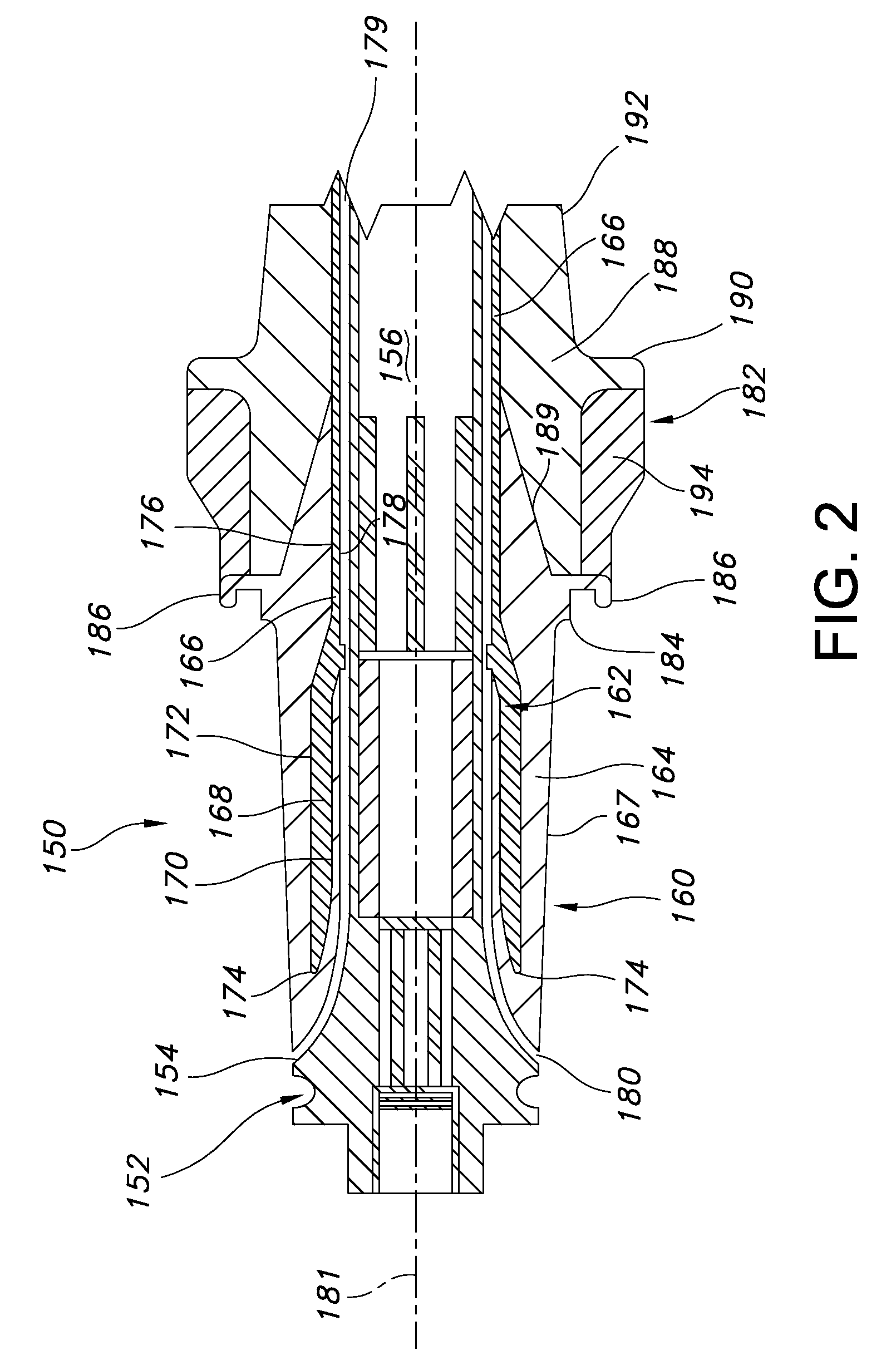
[0029]FIG. 2 is a cross sectional view of a connector bushing 150 formed in accordance with an exemplary embodiment of the invention. The bushing 150 may be used in lieu of the bushing connector 102 shown in FIG. 1 in the connector system 100. The bushing 150 is configured as a loadbreak connector, and accordingly includes a loadbreak contact assembly 152 including a contact tube 154, a piston contact element 156 having finger contacts that is movable within the contact tube in a fault closure condition and an arc-ablative component which produces an arc extinguishing gas in a known manner during loadbreak switching for enhanced switching performance. A hex broach 158 is also provided and may be used to tighten the connector bushing 150 to a stud terminal of a piece of electrical equipment.

[0030]Unlike the embodiment of FIG. 1, the bushing connector 150 includes a shield assembly 160 surrounding the contact assembly 152 that provides numerous benefits to users and manufacturers alik...

sixth embodiment

[0048]FIG. 7 is a cross sectional schematic view of a bushing connector 300 that, unlike the foregoing embodiments of FIGS. 2-6 that are loadbreak connectors, is a deadbreak connector.

[0049]The bushing connector 300 may be used with a mating connector, such as the connector 102 shown in FIG. 1 in a deadbreak separable connector system. The bushing connector 300 includes a shield 302 in the form of a contact tube 304, and a contact element 308 having finger contacts 310. The contact element 308 is permanently fixed within the contact tube 304 in a spaced position from an open distal end 312 of the connector in all operating conditions. The shield 302 may be connected to a piece of electrical equipment via, for example, a terminal stud 315.

[0050]Like the foregoing embodiments, an insulative or nonconductive housing interface member 306 may be formed on a surface of the shield 302 in, for example, an overmolding operation as explained above. Also, as explained above, the interface memb...


PUM


Abstract

A separable insulated connector assembly provided with a thermoplastic interface formed on a surface of a shield.

Description

BACKGROUND OF THE INVENTION[0001]The invention relates generally to cable connectors for electric power systems, and more particularly to separable insulated connector systems for use with medium voltage cable distribution systems.[0002]Electrical power is typically transmitted from substations through cables which interconnect other cables and electrical apparatus in a power distribution network. The cables are typically terminated on bushings that may pass through walls of metal encased equipment such as capacitors, transformers or switchgear. Such cables and equipment transmit electrical power at medium and high voltages generally greater than 600V.[0003]Separable connector systems have been developed that allow ready connection and disconnection of the cables to and from the electrical equipment. In general, two basic types of separable connector systems have conventionally been provided, namely deadbreak connector systems and loadbreak connector systems. Conventional connectors...

Claims


Application Information

Patent Timeline
Patent Type & Authority Patents(United States)
IPC IPC(8): H01R13/53
CPCH01R4/70H01R13/648Y10S439/921
Inventor HUGHES, DAVID CHARLESMAKAL, JOHN M.HEINIG, EDINE MARY
Owner COOPER TECH CO
Why Eureka
Try Eureka