Robotic tyre changing apparatus and associated hardware and methods

a technology of robots and tyres, applied in the field of robot tyre changing apparatuses, can solve the problems of exposing workers to crushing or explosion risk, tyres falling or exploding, and posing a substantial risk of injury

Inactive Publication Date: 2016-06-02
MACHINERY AUTOMATION & ROBOTICS
View PDF0 Cites 26 Cited by
  • Summary
  • Abstract
  • Description
  • Claims
  • Application Information

AI Technical Summary

Benefits of technology

[0017]Preferably the circular housing is sized so as to receive the lock ring whilst the gap in the lock ring is being maintained in a spread apart state by the spreader unit to thereby stablise the lock ring against twisting.

Problems solved by technology

Typically this involves the worker operating hand tools or mechanised nut runners (such as pneumatic impact drivers, or the like) to loosen and remove each of the nuts whilst working within a region that is unsafe due to a risk that the tyre may fall or explode.
Due to the size and weight of the lock ring, this poses a substantial risk of injury.
Such o-rings are typically manually removed and subsequently inserted by a worker and this manual process exposes the worker to a risk of crushing or exposure to an explosion.

Method used


Image

  • Robotic tyre changing apparatus and associated hardware and methods
  • Robotic tyre changing apparatus and associated hardware and methods
  • Robotic tyre changing apparatus and associated hardware and methods

Examples


Embodiment Construction

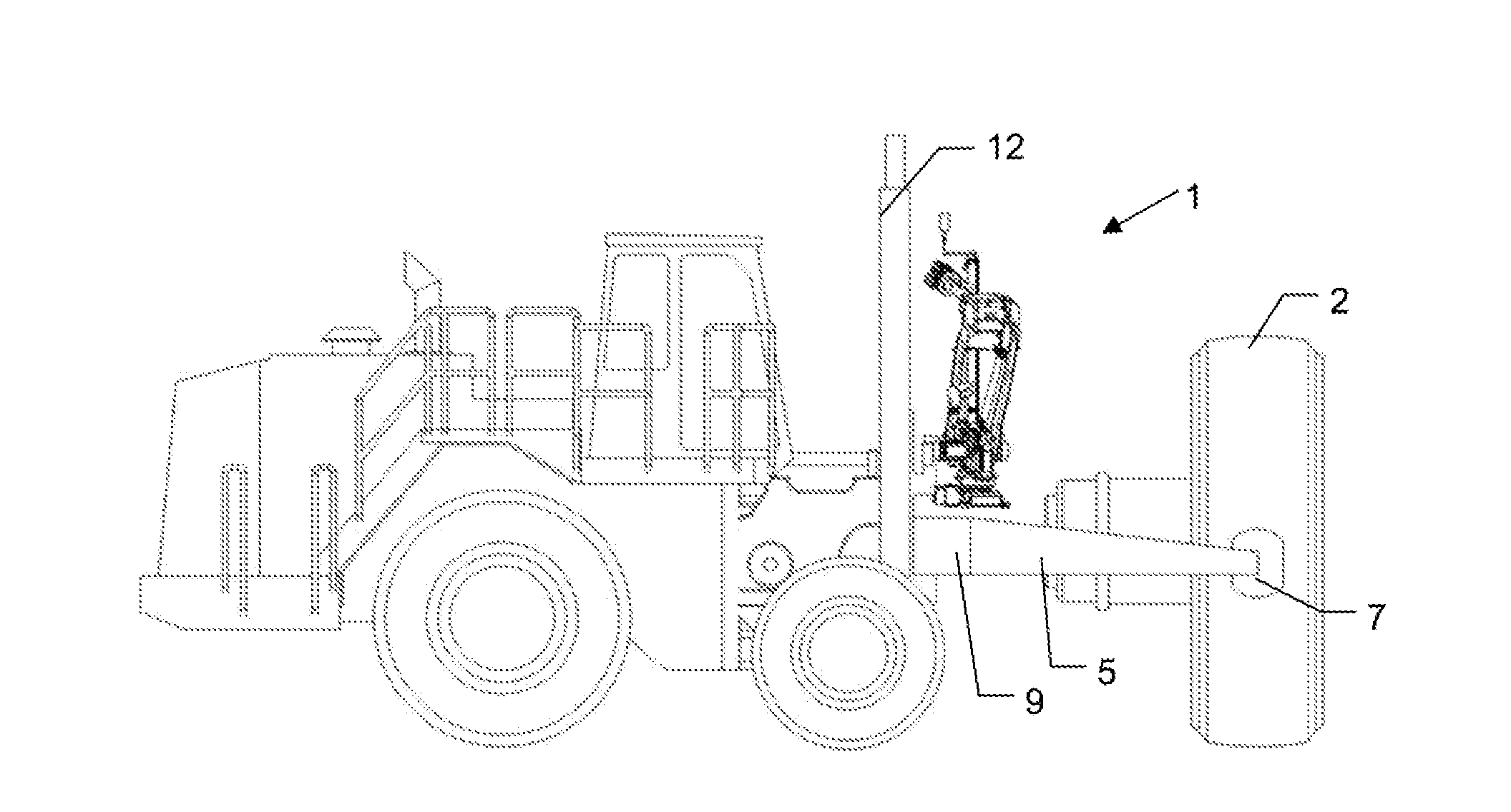
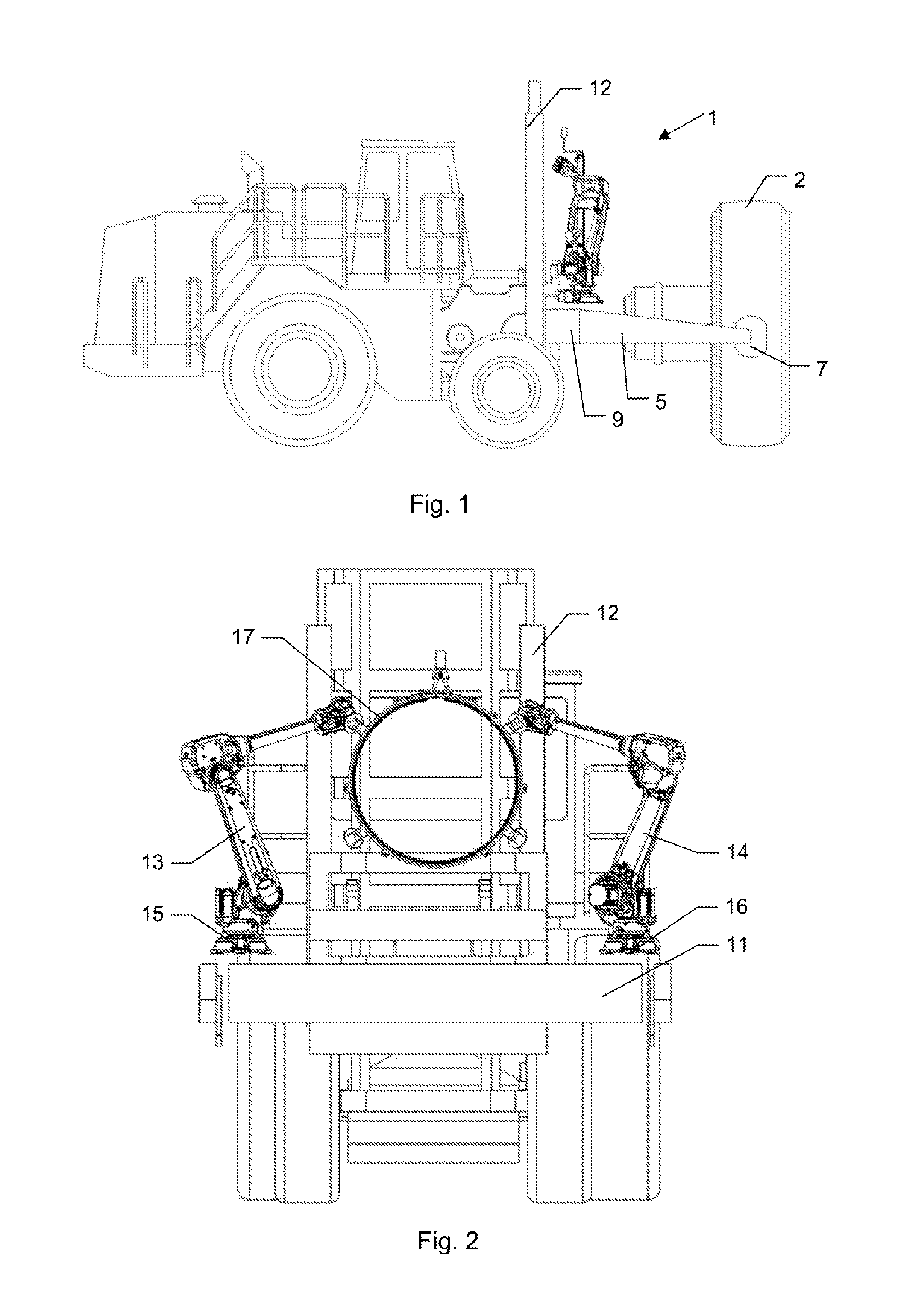
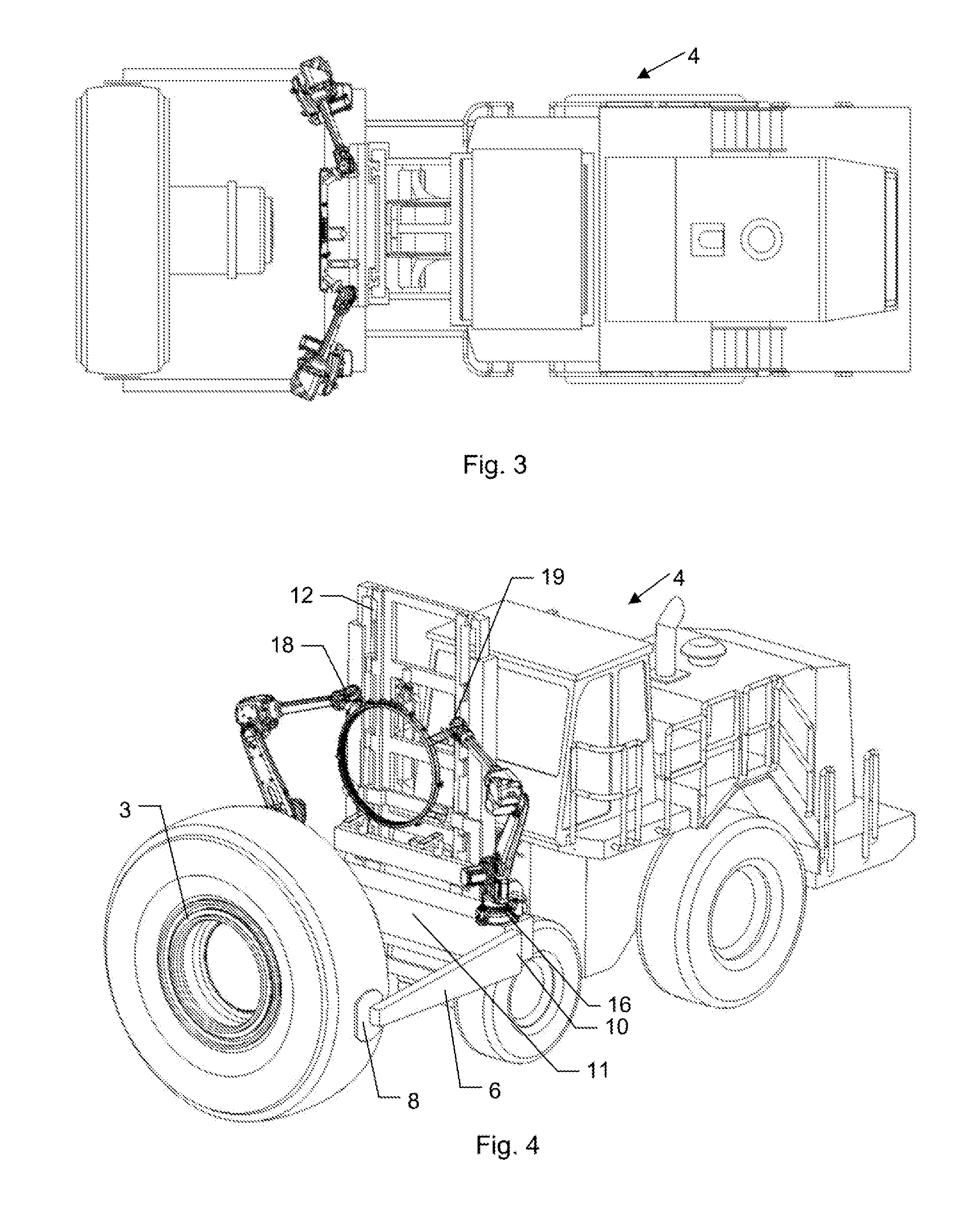
[0057]The embodiment of the tyre changing apparatus 1 as depicted for example in FIGS. 1 to 4 is for use with a tyre 2 disposed on a wheel 3 of the type commonly used for large haul trucks and in particular those typically employed in mining operations. The apparatus 1 includes a tyre handler 4, which may be any one of the various commercially available tyre handlers on the market, such as those marketed for example by: Iowa Mold Tooling Co. Inc, which is based in Garner, Iowa, USA; or Austin Engineering Ltd, which is based in Brisbane, Queensland, Australia; or Cascade Europe, which is based in El Amere, Netherlands. Such tyre handlers 4 are typically fork lift-type trucks that support two outwardly extending generally parallel arms 5 and 6, which respectively define distal ends 7 and 8. The operator of the tyre handler can manipulate the controls to cause the distal ends 7 and 8 of the arms 5 and 6 to clamp onto the tyre 2, which allows for manipulation of the large and heavy tyre...


PUM


Abstract

A tyre changing apparatus 1, for use with tyres on large haul trucks employed in mining operations. The apparatus includes a tyre handler. The grab unit of the tyre handler can provide a stable work platform from which robots may execute tasks. Hence, a first robot is disposed adjacent to the proximal end of arm and a second robot is disposed adjacent to the proximal end of the second arm. This apparatus may be utilised by the robots so as to spread the gap in a lock ring to assist when removing and installing the lock ring. An o-ring installation device may be utilized by the robots when installing an o-ring.

Description

FIELD OF THE INVENTION[0001]The present invention relates to a robotic tyre changing apparatus and associated hardware and methods. Embodiments of the present invention find application, though not exclusively, in the mining industry for use with the wheels and tyres of large haul trucks and dump trucks.BACKGROUND OF THE INVENTION[0002]Any discussion of documents, acts, materials, devices, articles or the like which has been included in this specification is solely for the purpose of providing a context for the present invention. It is not to be taken as an admission that any or all of these matters form part of the prior art base or were common general knowledge in the field relevant to the present invention as it existed in Australia or elsewhere before the priority date of this application.[0003]The removal of wheels and tyres from large mining haul trucks and dump trucks is typically achieved with the use of a mechanical wheel handler to support the wheel whilst a worker removes...

Claims


Application Information

Patent Timeline
Patent Type & Authority Applications(United States)
IPC IPC(8): B60C25/05B23P19/08B60B30/02B23P19/04B60C25/132B60B29/00
CPCB60C25/0515B60C25/132B60C25/0521B60B29/001B60B30/02B60B2340/50B23P19/084B60B2320/10B60B2320/50B60B2340/32B23P19/047B60B29/002B60Y2200/142B60Y2200/41
Inventor CAMPBELL, CLYDE
Owner MACHINERY AUTOMATION & ROBOTICS
Why Eureka
Try Eureka