Rendering and Lightmap Calculation Methods

a calculation method and lightmap technology, applied in the field of rendering and lightmap calculation methods, can solve the problems of inability to carry out actions such as separate or select individual parts of the model, inability to quickly propagate changes in the cad model, and inability to quickly solve current solutions, etc., to achieve automatic reduction of the number of polygons, without increasing the size of the scene geometry or its loading time.

Inactive Publication Date: 2016-06-02
BEVELITY
View PDF7 Cites 32 Cited by
  • Summary
  • Abstract
  • Description
  • Claims
  • Application Information

AI Technical Summary

Benefits of technology

[0020]An object of the invention is to enable scenes imported directly from CAD programs to be rendered in real time with photo-realistic quality without requiring manual optimization and also maintaining the original elements of the 3D model.
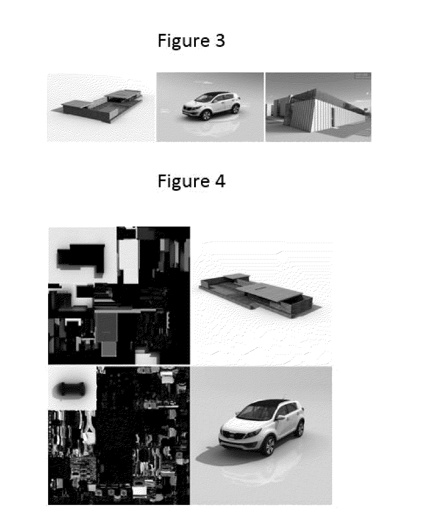
[0038]With regards to the textures, there is an algorithm that enables the loading of textures to the memory of the device to be adjusted whilst maintaining the maximum quality perceived by the user. In order to do so, the images are divided depending on their function: texture, normal map, lightmap, UI image. The algorithm automatically selects the quality of each texture so that the scene does not exceed the limits of the device or PC's memory. When a 3D scene is loaded, most of the memory is divided between the geometry and the textures, and on average the memory required for textures is 5 to 10 times greater than the memory required for the geometry, hence the importance of optimizing the textures (FIG. 5).

Problems solved by technology

One of the bottlenecks when rendering complex scenes is the communication between the CPU (central processing unit) and the GPU, which occurs every time the material, texture of geometry is changed.
When a complex 3D model is imported directly from a CAD application, without prior manual optimization that reduces the thousands or tens of thousands of small objects, all the current solutions are unable to draw the model quickly enough (12 fps).
Moreover, it must be noted that when the user manually optimizes the 3D model, thus reducing the number of elements, the final model that used is not the same as the original model, such that, on the one hand, the changes in the CAD model cannot be propagated into the imported model, and on the other hand, it is not possible to carry out actions such as separate or select individual parts of the model.
Another problem that currently exists is that the scene lighting needs to be pre-calculated via lightmaps in order to be able to represent the 3D scene photo-realistically and efficiently.
This poses two problems: one is that these methods are incompatible with the concept of instances since each object needs its own UV coordinate map and, therefore, it is not possible to reuse the same geometry, drawing it in different positions, and therefore new geometries must be created.
The second is that the current systems either generate a single map with all the objects, which is insufficient in order to obtain the necessary quality, or generate a map for each object, which does not enable the scene to be correctly optimized.
This means that the process for configuring the scene lighting is long and complex.

Method used


Image

  • Rendering and Lightmap Calculation Methods
  • Rendering and Lightmap Calculation Methods
  • Rendering and Lightmap Calculation Methods

Examples


Embodiment Construction

[0051]What follows is a brief description of an embodiment of the invention by way of illustrative and non-limiting examples thereof.

[0052]As mentioned above, the main technical factors that determine the drawing speed of the scenes are:[0053]Number of CPU-GPU calls (draw calls).[0054]Change of textures.[0055]Number of polygons in the scene.[0056]Size of textures.

[0057]Therefore, these numbers must be reduced and for which reason the process is as follows:

[0058]In order to reduce the number of draw calls and the change of textures, the objects of the scene are drawn grouped together by material and texture. When a scene formed of single geometries and the instances that they refer to is loaded, the instances are grouped according to their material and a new geometry is calculated for each group, joining and transforming each geometry into a common coordinate system, in such a way that the drawing of several instances is subsequently substituted by the drawing of a single object in a...


PUM


Abstract

A rendering method that comprises defining islands of connected triangles whose difference between normals is less than the geometries of the instances, and putting them in boxes, and in that said boxes are in turn grouped into cubes, prior to calculating the lightmaps. Said grouping may be by material and textures, and the method shall define each box inside the cube by its two end coordinates.It likewise comprises a method for calculating lightmaps by dividing into three different textures: direct lights, ambient illumination or occlusion and sunlight, and calculating them independently.

Description

CROSS REFERENCE TO RELATED APPLICATIONS[0001]This application claims the benefit of U.S. Provisional Patent Application Ser. No. 62 / 084,795 filed Nov. 26, 2014 entitled “Rendering and Lightmap Calculation Method”, which is incorporated by reference herein in its entirety.FIELD OF APPLICATION[0002]The present invention relates to a rendering method that may be applied in real time and a lightmap calculation method that enables high quality results to be obtained in a very short processing time.STATE OF THE ART[0003]In all professional areas in which 3D models are created in order to improve the production processes, it is necessary to be able to simply and quickly share and view these models with all the project members, including clients, in order to be able to analyze the state of the project or deigns and be able to thus persuade or make decisions. For this, it is essential for the model to be easily accessible, online and from devices or personal computers, and for the viewing qu...

Claims


Application Information

Patent Timeline
Patent Type & Authority Applications(United States)
IPC IPC(8): G06T15/50G06T17/20G06T15/04G06T15/10
CPCG06T15/506G06T15/04G06T17/20G06T15/10G06T2215/12
Inventor IBORRA OLBA, DANIEL
Owner BEVELITY
Why Eureka
Try Eureka