Procedure for mapping when capturing video streams by means of a camera

a technology of video stream and camera, applied in the field of camera, can solve the problems of not fully covering the optimal integration time position, not enough to achieve the effect of maximum quality in every scen

Active Publication Date: 2017-05-09
FLIR SYST AB
View PDF9 Cites 1 Cited by
  • Summary
  • Abstract
  • Description
  • Claims
  • Application Information

AI Technical Summary

Benefits of technology

[0006]The object of the present invention is to make available a procedure which adapts the integration time dynamically on the basis of the scene content in order to achieve maximum quality in every scene without the need for constant updates of maps by NUC processing and without having to store maps for a large number of fixed integration times.
[0008]The use of reference images, the most recent updating of the offset map and its integration time, as well as linear interpolation, permits a compensation map to be created which corresponds closely to the actual integration time. The procedure permits the integration time to be changed continuously and entirely automatically without needing to undergo a further NUC process.
[0011]According to an advantageous procedure, specifically two reference images are recorded in production against a black-body radiator at the same temperature for two separate integration times. By restricting the number of reference images to two, the mapping process can be kept relatively simple from the point of view of storage and calculation.

Problems solved by technology

The disadvantage of fixed integration times is that deviations in the image quality are necessary in order to be able to cover a particular dynamic range, since the image quality is optimized only at a single scene temperature.
Several fixed integration time positions have been introduced in order to increase the image quality, which improves the image quality at the expense of higher complexity but still does not fully cover optimal integration time positions.
One disadvantage associated with this is that it involves making a shift away from the integration time which was relevant at the time when the maps were made.
This shift away from the integration time at the time when the maps were made gives rise to a low-frequency unevenness of the image.

Method used


Image

  • Procedure for mapping when capturing video streams by means of a camera
  • Procedure for mapping when capturing video streams by means of a camera
  • Procedure for mapping when capturing video streams by means of a camera

Examples


Embodiment Construction

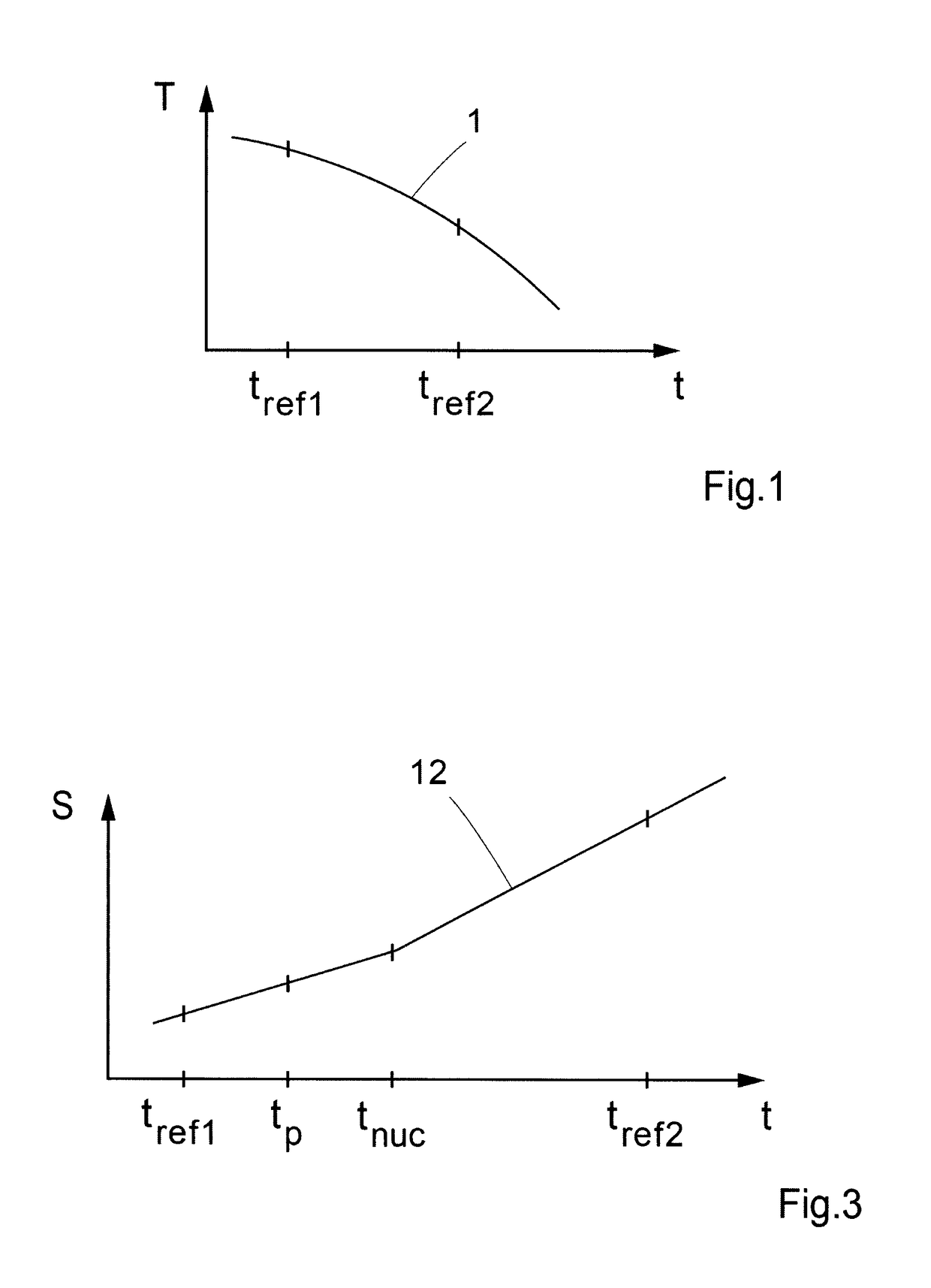
[0018]The curve 1 depicted in FIG. 1 depicts an example of the scene temperature T as a function of the integration time t for optimized image quality. Two fixed integration times t1 and t2 are plotted in the Figure. According to the known method, an individual map is connected to each integration time. In the event that another suitable integration time is used, a shift will take place from the integration times for which the maps were produced, and low-frequency unevennesses of the image will occur as a result. According to the proposed procedure for mapping, which is described in more detail with reference to FIG. 2, compensation maps are generated which offer relevant mapping along the scene temperature curve between fixed references.

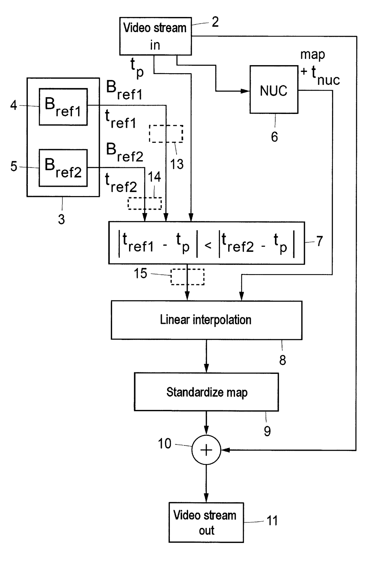
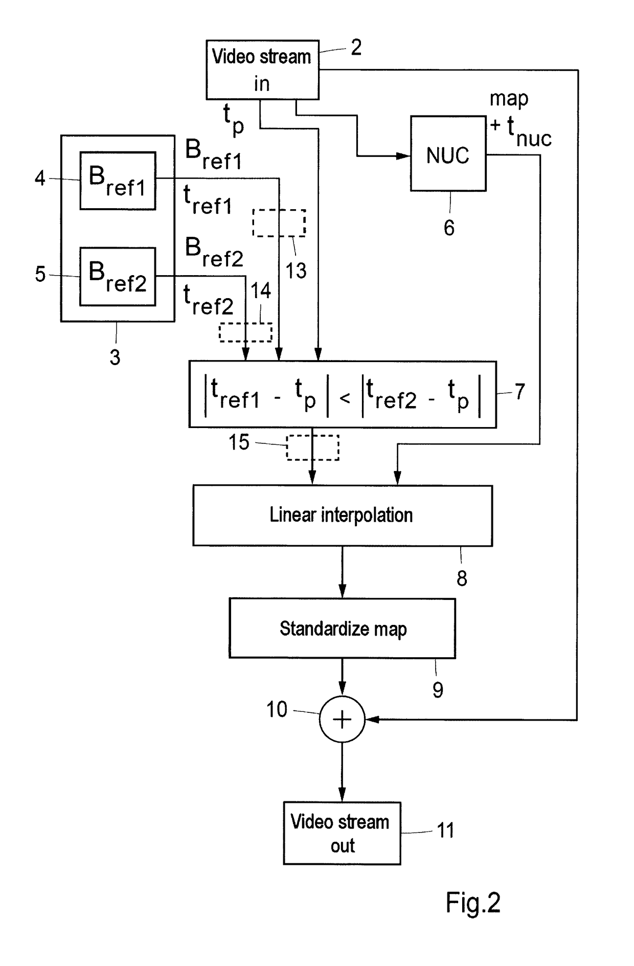
[0019]The principles for mapping according to the procedure of the invention are now described with reference to FIG. 2.

[0020]An incoming video stream is available through a block 2. The stream can be supplied from the sensor part of an IR camera, t...


PUM


Abstract

The invention relates to a procedure for mapping when capturing video streams by means of a camera, such as an IR camera, as well as to a computer program and a computer program product. According to the procedure the following items are included: a) at least two reference images are recorded in production against a black-body radiator at the same temperature for two or more separate integration times (block 3), b) in conjunction with the updating of an offset map, details of the integration time for which the offset map has been updated are stored (block 6), c) during operation, the actual integration time is compared with the integration time for the most recent updating of the offset map (block 8), d) the recorded reference image which lies closest to the actual integration time is selected as a reference (block 7), and e) a compensation per pixel for the change in the integration time is calculated by linear interpolation between the selected reference image and the most recently updated offset map, resulting in a compensation map (block 8). The integration time can be adapted dynamically by the procedure with access to adequate maps for correction of the offset of constituent pixels.

Description

TECHNICAL FIELD[0001]The present invention relates to a procedure for mapping when capturing video streams by means of a camera, such as an IR camera, as well as to a computer program and a computer program product.BACKGROUND[0002]The output signal from sensor elements in a sensor, such as a focal plane array, IR FPA, contained in a camera can vary quite considerably as a function of the irradiated effect. Sensor elements thus require to be calibrated with one another. The sensor elements contained in a sensor in an IR camera do not behave in the same way, for example, but exhibit variations in gain and offset. In order to manage these variations, so-called gain maps and offset maps are recorded and stored in production. With the help of the gain map, corrections are made during operation for variations in gain in the individual sensor elements in a sensor. The offset map is used correspondingly to shift the sensor signals of the constituent sensor elements in parallel during operat...

Claims


Application Information

Patent Timeline
Patent Type & Authority Patents(United States)
IPC IPC(8): H04N7/18H04N5/33H04N17/00G01J5/00G01J5/80G01J5/90H04N25/671
CPCH04N5/33H04N17/002G01J5/00G01J5/90G01J5/80H04N25/671
Inventor JOHANSSON, EMANUELLARSON, ODD
Owner FLIR SYST AB
Why Eureka
Try Eureka