Reflector-mirror drive shaft controller for laser beam machine

Inactive Publication Date: 2005-12-01
YAMAZAKI MAZAK CORPORATION
View PDF9 Cites 3 Cited by
  • Summary
  • Abstract
  • Description
  • Claims
  • Application Information

AI Technical Summary

Benefits of technology

[0016] Also, it comprises a reflector-mirror which is moved along a drive shaft to keep length of an optical path between the laser oscillator device and the machining lens constant, and means for giving an offset to movement of the reflector-mirror, thereby adjusting diameter size of a beam incident to the machining lens to keep the diameter size constant.
[0018] By movably installing the reflector-mirror which has an NC drive shaft, the present invention makes it possible to vary the beam incident to the machining lens continuously, and thereby provide the maximum machining quality and machining speed over the entire thickness range between a and b.
[0019] Thus, the present invention provides the best machining quality and productivity over the entire thickness range between a and b using a machining lens with a single focal length.

Problems solved by technology

However, when the material and workpiece thickness change continuously, it is practically impossible to prepare machining lenses of focal lengths which vary continuously and steplessly, making it necessary to prepare several machining lenses of typical focal lengths which vary stepwise (e.g., 2.5 inches, 3.5 inches, 5.0 inches, 7.5 inches, etc.) based on experience.
Similarly, there also exists a maximum machining speed between a and b, meaning that the maximum machining speed is not available for every workpiece thickness.
Thus, maximum productivity is not available.

Method used


Image

  • Reflector-mirror drive shaft controller for laser beam machine
  • Reflector-mirror drive shaft controller for laser beam machine
  • Reflector-mirror drive shaft controller for laser beam machine

Examples


Embodiment Construction

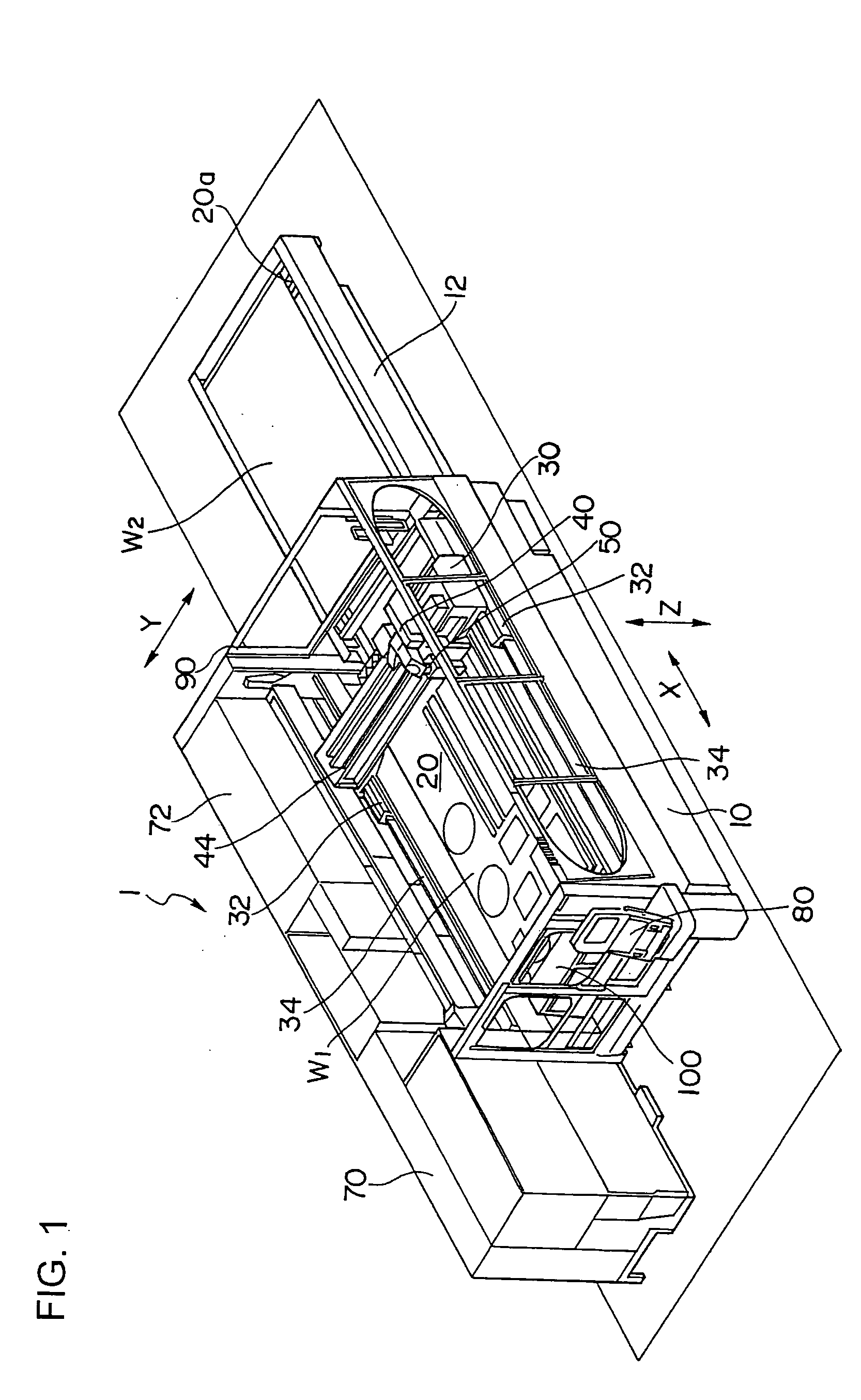
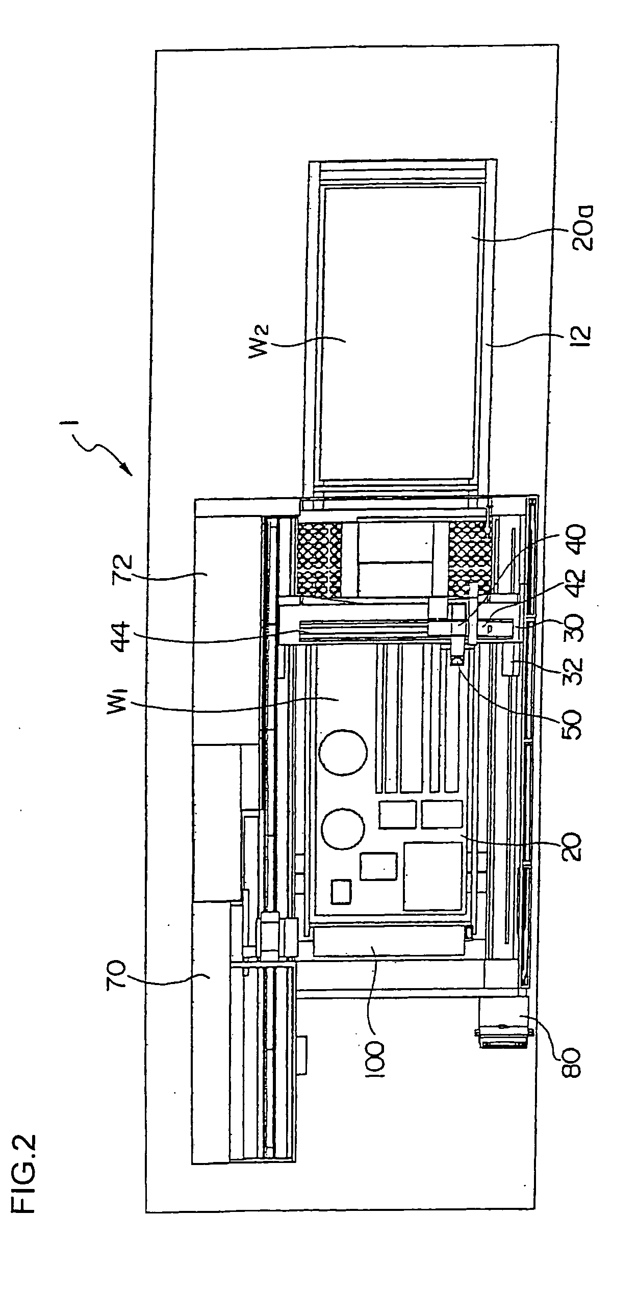
[0031]FIG. 1 is a perspective view showing an overall configuration of a laser beam machine according to the present invention, FIG. 2 is a plan view, FIG. 3 is a front view, FIG. 4 is a perspective view of the relevant portion, and FIG. 5 is a side view.

[0032] A laser beam machine, generally denoted by reference number 1, has a pallet (table) 20 which is disposed on a bed 10 to carry a plate-shaped workpiece W1. A pallet changer 12 is placed on the longitudinal extension of the bed 10, and a pallet 20a carrying a workpiece W2 to be machined next is awaiting its turn.

[0033] A pair of guide rails 34 are installed on both sides of the bed 10 along its length and a column 30 is mounted on the guide rails 34 in such a way as to be movable along an X axis.

[0034] Means for driving the column 30 along the X axis is provided by, for example, a linear motor, which is formed by a stator installed on the guide rails 34 and a moving member installed on a linear-motion guide 32.

[0035] A guid...


PUM

PropertyMeasurementUnit
Lengthaaaaaaaaaa
Thicknessaaaaaaaaaa
Diameteraaaaaaaaaa

Abstract

The invention provides a reflector-mirror drive shaft controller for laser beam machine which optimizes a beam for workpiece thickness by correcting a control axis of a laser reflector-mirror of a laser beam machine. A laser beam outputted from a laser oscillator device 550 of a laser beam machine is reflected by a reflector-mirror 570 via an output mirror 560 and introduced into a laser machining tool 60. When a machining head moves along an X axis, the reflector-mirror is moved along a U axis parallel to the X axis to keep optical path length constant. By giving an offset a to U axis control, the incident beam diameter D of the machining lens is varied to form an optimum machining beam for workpiece thickness.

Description

[0001] The present application is based on and claims priority of Japanese patent application No. 2004-155943 filed on May 26, 2004, the entire contents of which are hereby incorporated by reference. BACKGROUND OF THE INVENTION [0002] 1. Field of the Invention [0003] The present invention relates to a reflector-mirror drive shaft controller which makes it possible to use unskilled operators in operating a laser beam machine, maximize quality and productivity for each material and workpiece thickness, and accomplish long, unattended operation under optimum machining conditions. [0004] 2. Description of the Related Art [0005] Conventionally, laser machining involves placing a lens at an end of an optical path of a laser beam emitted from a laser oscillator device, setting a workpiece near the focal position of the lens, and machining the workpiece through instantaneous evaporation. [0006] The focal length of the machining lens greatly affects machining and the optimum focal length var...

Claims


Application Information

Patent Timeline
IPC IPC(8): B23K26/00B23K26/04B23K26/064
CPCB23K26/06B23K26/1482B23K26/0876B23K26/0869
Inventor YAMAZAKI, TSUNEHIKOMIYAKAWA, NAOOMI
Owner YAMAZAKI MAZAK CORPORATION
Why Eureka
Try Eureka