Scanning unit and image forming apparatus

a scanning unit and image forming technology, applied in the field of scanning units, can solve the problems of increasing noise and power consumption, reducing the durability of polygon scanning, and difficulty in coupling lenses,

Active Publication Date: 2008-05-29
RICOH KK
View PDF21 Cites 67 Cited by
  • Summary
  • Abstract
  • Description
  • Claims
  • Application Information

AI Technical Summary

Benefits of technology

[0016]It is an object of the present invention to at least

Problems solved by technology

However, if the polygon scanner is rotated a high speed, noise and power consumption increases and durability of the polygon scanner drops.
In the scheme (1), a low price can be realized because general-purpose lasers can be used, but using a plurality of beams to stably maintain a relative positional relationship between the lasers and a coupling lens is difficult, and an interval between a plurality of scan lines formed on a scanning target surface (hereinafter, “scan line interval”) may possibly become

Method used


Image

  • Scanning unit and image forming apparatus
  • Scanning unit and image forming apparatus
  • Scanning unit and image forming apparatus

Examples


first embodiment

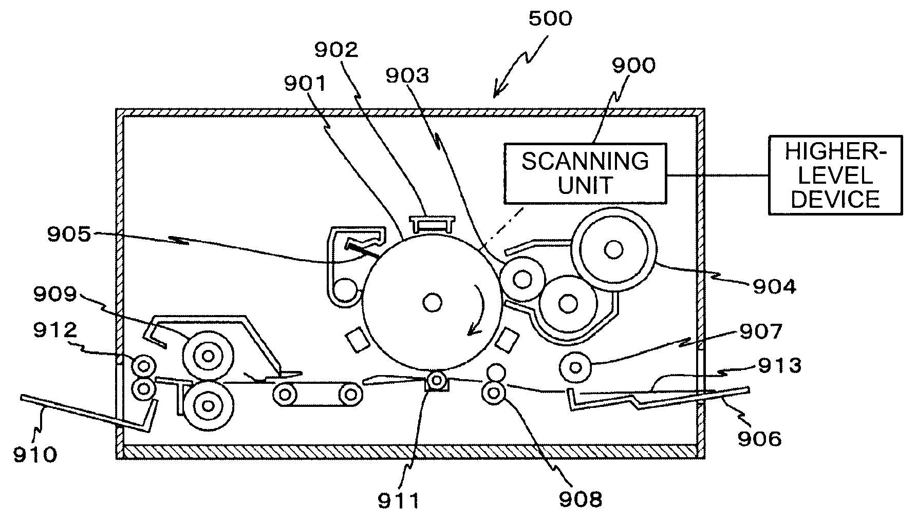
[0042]FIG. 1 is a schematic diagram of a laser printer 500 as an image forming apparatus according to the present invention.

[0043]The laser printer 500 includes a scanning unit 900, a photosensitive drum 901, a charger 902, a developing roller 903, a toner cartridge 904, a cleaning blade 905, a sheet-feed tray 906, a sheet-feed roller 907, a pair of registration rollers 908, a fixing roller 909, a sheet-discharge tray 910, a transfer charger 911, and a pair of sheet-discharge rollers 912.

[0044]The charger 902, the developing roller 903, the transfer charger 911, and the cleaning blade 905 are arranged around and close to the periphery of the photosensitive drum 901 and in the above-mentioned order along the rotating direction of the photosensitive drum 901 (clockwise direction indicated by an arrow in FIG. 1).

[0045]A photosensitive layer is laid on the surface of the photosensitive drum 901. In other words, the surface of the photosensitive drum 901 is a target surface for scanning ...


PUM


Abstract

A scanning unit in an image forming apparatus includes a light source, a coupling lens, an aperture, an image forming lens, and a polygon mirror. The light source includes a plurality of surface-emitting lasers. The coupling lens, the aperture, and the image forming lens are arranged on the optical path of light beams emitted by the light source. The polygon mirror deflects light beams of an image formed by the coupling lens towards a photosensitive drum for scanning. The focal length of the image forming lens in a sub-scanning direction is set to be equal to or smaller than an optical path length between the image forming lens and the aperture.

Description

CROSS-REFERENCE TO RELATED APPLICATIONS[0001]The present application claims priority to and incorporates by reference the entire contents of Japanese priority document, 2006-316751 filed in Japan on Nov. 24, 2006.BACKGROUND OF THE INVENTION[0002]1. Field of the Invention[0003]The present invention generally relates to an scanning unit and specifically relates to an optical scanning unit.[0004]2. Description of the Related Art[0005]Image forming apparatuses that employ laser are being widely used for printing electronic images. Such an image forming apparatus typically includes a scanning unit and a photosensitive drum. The scanning unit includes a polygon scanner (e.g., a polygon mirror) that deflects laser toward the photosensitive drum, which is rotating, thereby scanning the surface of the photosensitive drum with the laser. Due to such scanning, a latent image is formed on the surface of the photosensitive drum. In image forming apparatuses, image density must be increased to ha...

Claims


Application Information

Patent Timeline
IPC IPC(8): H04N1/04
CPCH04N1/1135G02B26/124
Inventor HAYASHI, YOSHINORIWATANABE, NAOTOICHII, DAISUKEKUBO, NOBUAKI
Owner RICOH KK
Why Eureka
Try Eureka