connector

a technology of connecting rods and peripheral parts, applied in the direction of connection, coupling device connection, electrical apparatus, etc., can solve the problem of damage to the warp-preventing portion, and achieve the effect of preventing the interference between the locking arm and the peripheral member, and preventing the damage caused by displacemen

Active Publication Date: 2016-06-09
YAZAKI CORP
View PDF22 Cites 30 Cited by
  • Summary
  • Abstract
  • Description
  • Claims
  • Application Information

AI Technical Summary

Benefits of technology

[0019]In the connector, since the end surface in the longitudinal direction of the locking arm is positioned inside the end surface in the longitudinal direction of each of the locking arm protective walls, the locking arm protective walls can securely protect the locking arm and interference b...

Problems solved by technology

Thus, since strength of the warp-preventing portion lowers, when the locked portion and the warp-...

Method used


Image

  • connector
  • connector
  • connector

Examples


Embodiment Construction

[0029]A connector according to an embodiment of the present invention will be described below with reference to FIGS. 1 to 6C.

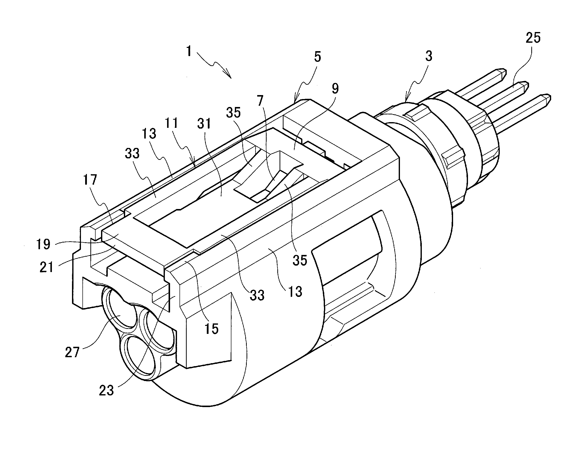
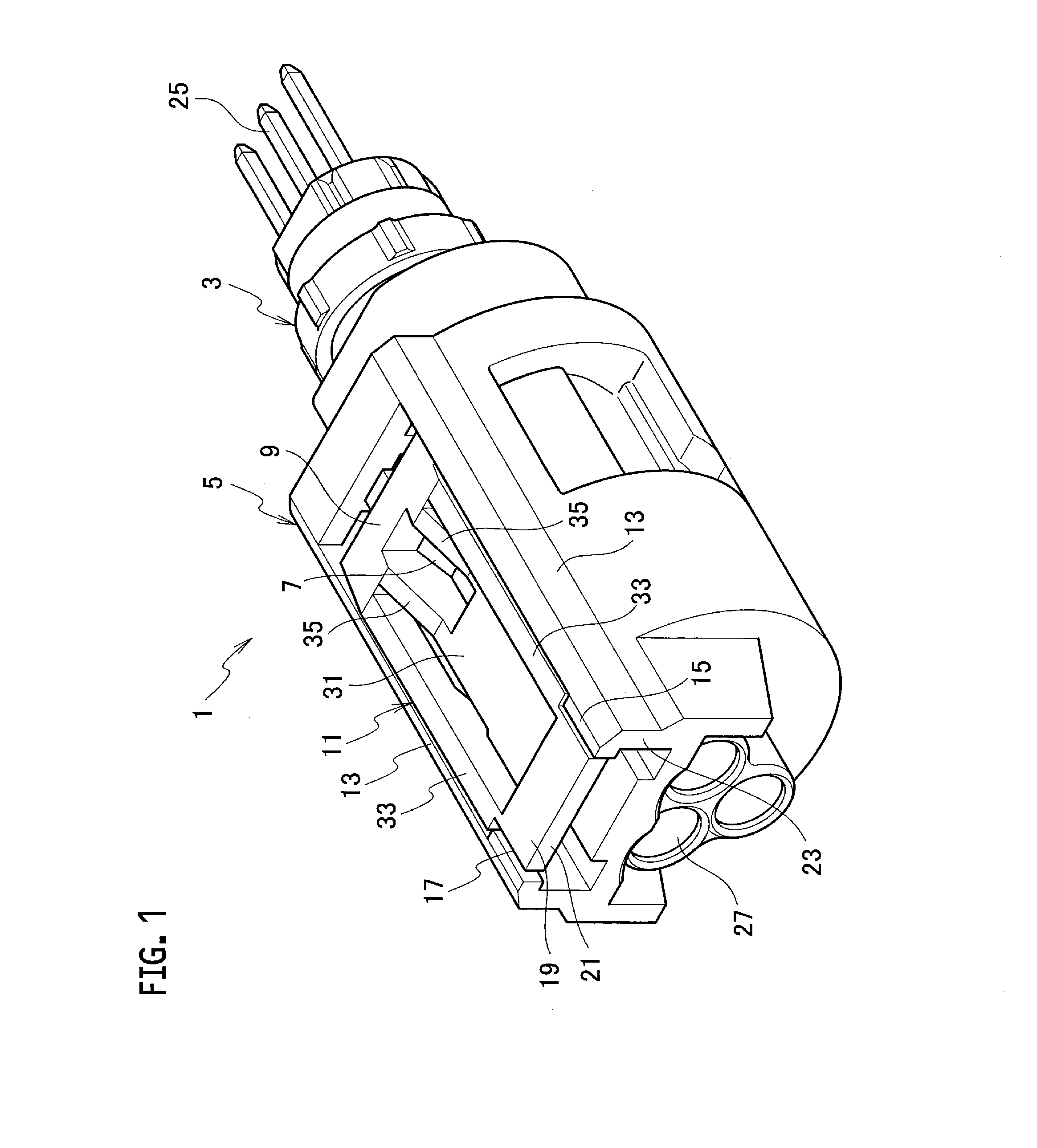
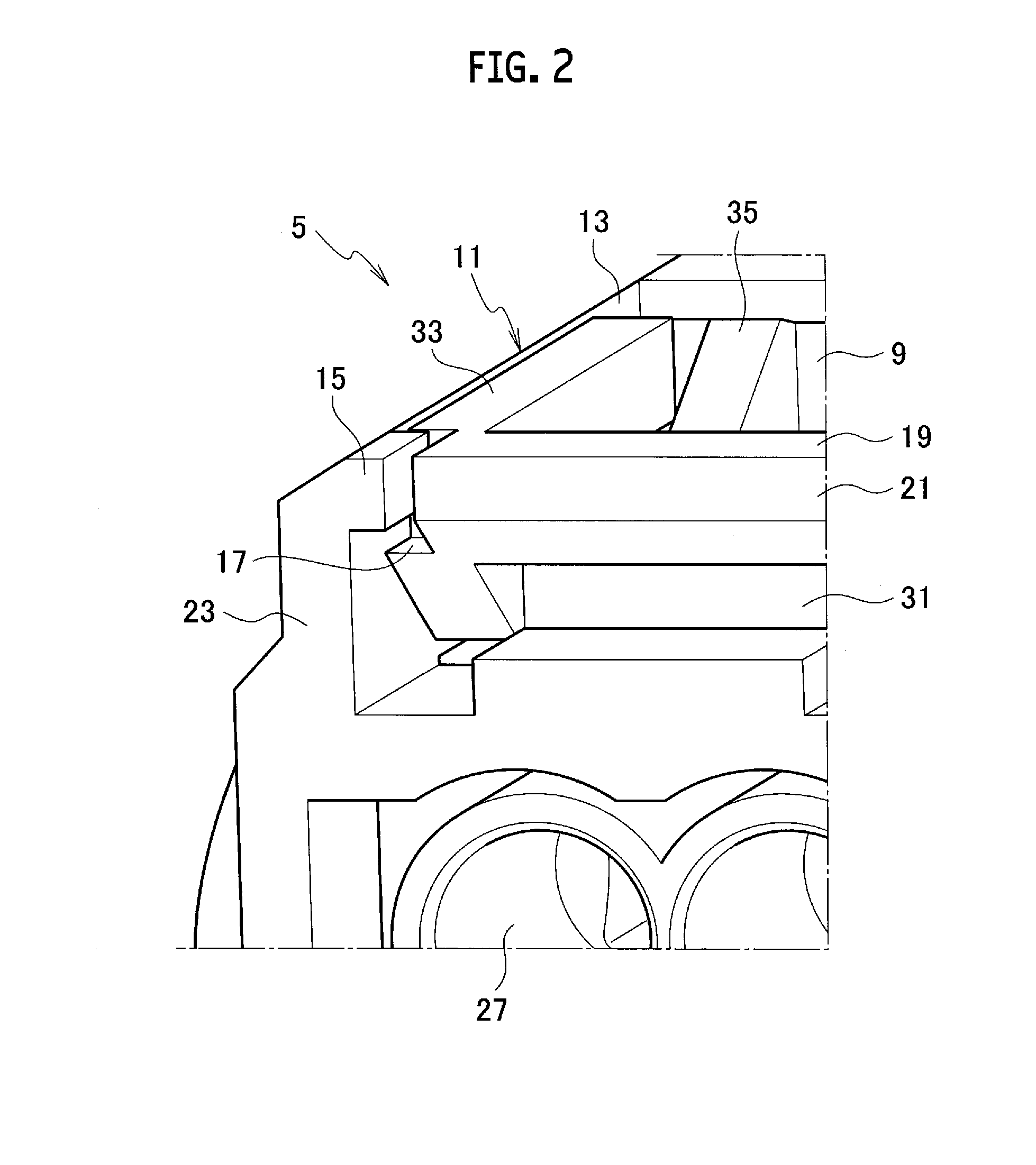
[0030]A connector 1 according to the present embodiment includes a housing 5, a locking arm 11, and locking arm protective walls 13, 13. The housing 5 is capable of fitting with a mating housing 3. The locking arm 11 is swingably disposed on the housing 5, and has a locking portion 9 capable of locking with a locked portion 7 of the mating housing 3. The locking arm protective walls 13, 13 are disposed in the housing 5 and are arranged on both sides in a width direction of the locking arm 11.

[0031]Each of the locking arm protective walls 13 includes an engaging protrusion 15 disposed so as to protrude toward the locking arm 11. The locking atm 11 includes an engaging recess portion 17. The engaging recess portion 17 is positioned on a surface facing each of the locking arm protective walls 13, engages with the engaging protrusion 15, and regulates displacemen...


PUM


Abstract

A connector includes a housing capable of fitting with a mating housing, a locking arm swingably disposed on the housing and having a locking portion capable of locking with a locked portion of the mating housing, and locking arm protective walls disposed on the housing and arranged on both sides in a width direction of the locking arm. An engaging protrusion is disposed on each of the locking arm protective walls so as to protrude toward a side of the locking arm. An engaging recess portion is disposed on the locking arm. The engaging recess portion is positioned on a surface facing each of the locking arm protective walls, engages with the engaging protrusion, and regulates displacement toward one side of a swinging direction of the locking arm.

Description

CROSS REFERENCE TO RELATED APPLICATIONS[0001]This application claims the priority of Japanese Patent Application No. 2014-247569, filed on Dec. 8, 2014, the entire content of which are incorporated herein by reference.BACKGROUND[0002]1. Technical Field[0003]The present invention relates to a connector.[0004]2. Related Art[0005]In the related art, a connector including a housing, a locking arm, and locking arm protective walls, has been known. The housing is capable of fitting with a mating housing. The locking arm is swingably disposed on the housing and has a locking portion capable of locking with a locked portion of the mating housing. The locking arm protective walls are disposed on the housing and are arranged at least on both sides in a width direction of the locking arm (refer to JPH 10-199621 A).[0006]In the connector, the locked portion is disposed so as to protrude on each of the sides in the width direction of the locking arm. A warp-preventing piece that locks with the l...

Claims


Application Information

Patent Timeline
IPC IPC(8): H01R13/627
CPCH01R13/6272
Inventor SEKINO, TETSUYA
Owner YAZAKI CORP
Why Eureka
Try Eureka