
Laminated ball joint connection device between a rotorcraft rotor blade and a lead/lag damper of said blade

a technology of lag damper and ball joint, which is applied in the direction of rotorcraft, vehicles, aircrafts, etc., can solve the problems of complex individual behavior of blades moving on the hub, dangerous resonance phenomena, etc., and achieve limit the maintenance operation of the rotor, constrain the effect of cost and constrain

Inactive Publication Date: 2016-06-16
EUROCOPTER
View PDF3 Cites 1 Cited by
  • Summary
  • Abstract
  • Description
  • Claims
  • Application Information

AI Technical Summary

Benefits of technology

The invention aims to create a connection device that is easy to maintain, minimizes the risk of damage to the rotor and is lightweight and compact. This is important for reducing costs and ensuring safety in aviation.

Problems solved by technology

Nevertheless, the individual behavior of blades moving on a hub is known to be complex.
Such resonance phenomena are known to be dangerous when the lead / lag movement of the blades about their lead / lag axes produces dynamic excitation in a stationary reference frame at a “regressive” frequency that is close to the resonant frequency of the aircraft on the ground or in flight.
However, the movements of the blade under consideration in terms of pitch variation and vertical flapping transmit a large amount of torque to the lead / lag damper, which torque is then taken up by the laminated ball joint.

Method used


Image

  • Laminated ball joint connection device between a rotorcraft rotor blade and a lead/lag damper of said blade
  • Laminated ball joint connection device between a rotorcraft rotor blade and a lead/lag damper of said blade
  • Laminated ball joint connection device between a rotorcraft rotor blade and a lead/lag damper of said blade

Examples


Embodiment Construction

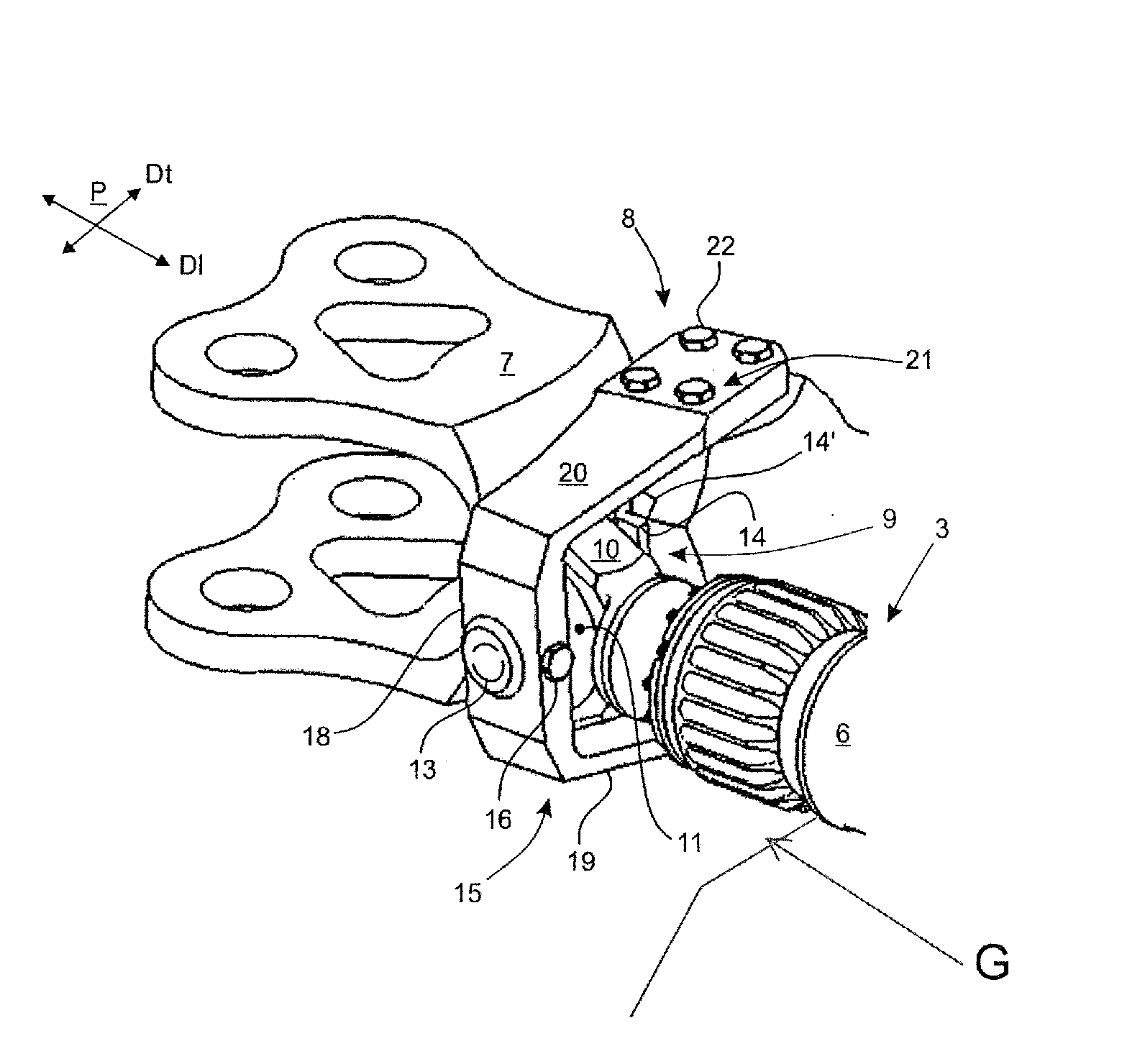
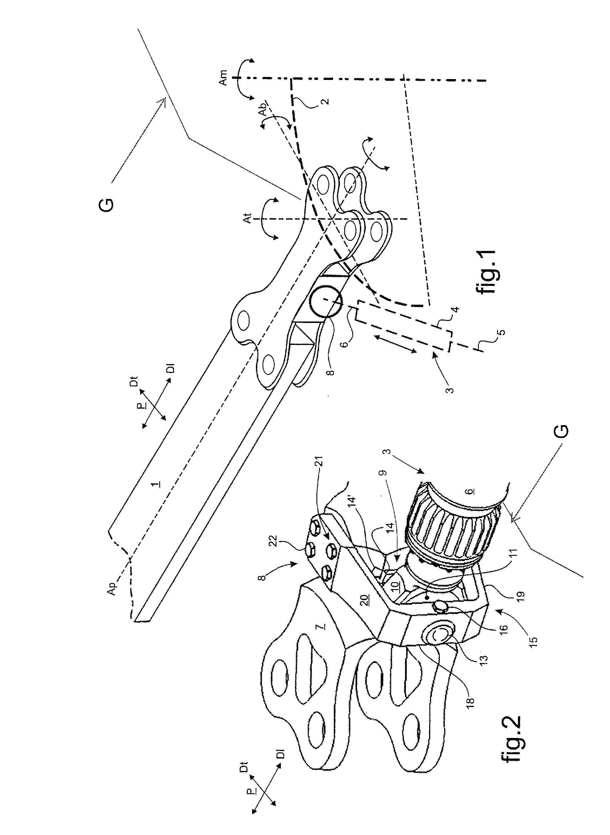
[0081]In FIG. 1, a blade 1 of a rotorcraft rotor G is mounted on a hub 2 of the rotor, typically being movable in pivoting relative to the hub 2 about a plurality of movement axes, including a pitch variation axis Ap, a flapping axis Ab, and a lead / lag axis At.

[0082]The pitch variation axis Ap extends in the general longitudinally-extending direction of said blade 1. The flapping axis Ab extends in the general transversely-extending direction of said blade 1, transversely to the axis of rotation Am of the hub 2 in its general plane of rotation. The lead / lag axis At extends perpendicularly to the general plane of the blade 1 or indeed essentially parallel to the axis of rotation Am of the hub 2, making allowance for pivoting variations of the blade 1 about its various movement axes, and in particular about its flapping axis Ab and about its pitch variation axis Ap.

[0083]In this context, the blade 1 is fitted with a lead / lag damper 3 essentially constituted by damper means 4 provided ...


PUM


Abstract

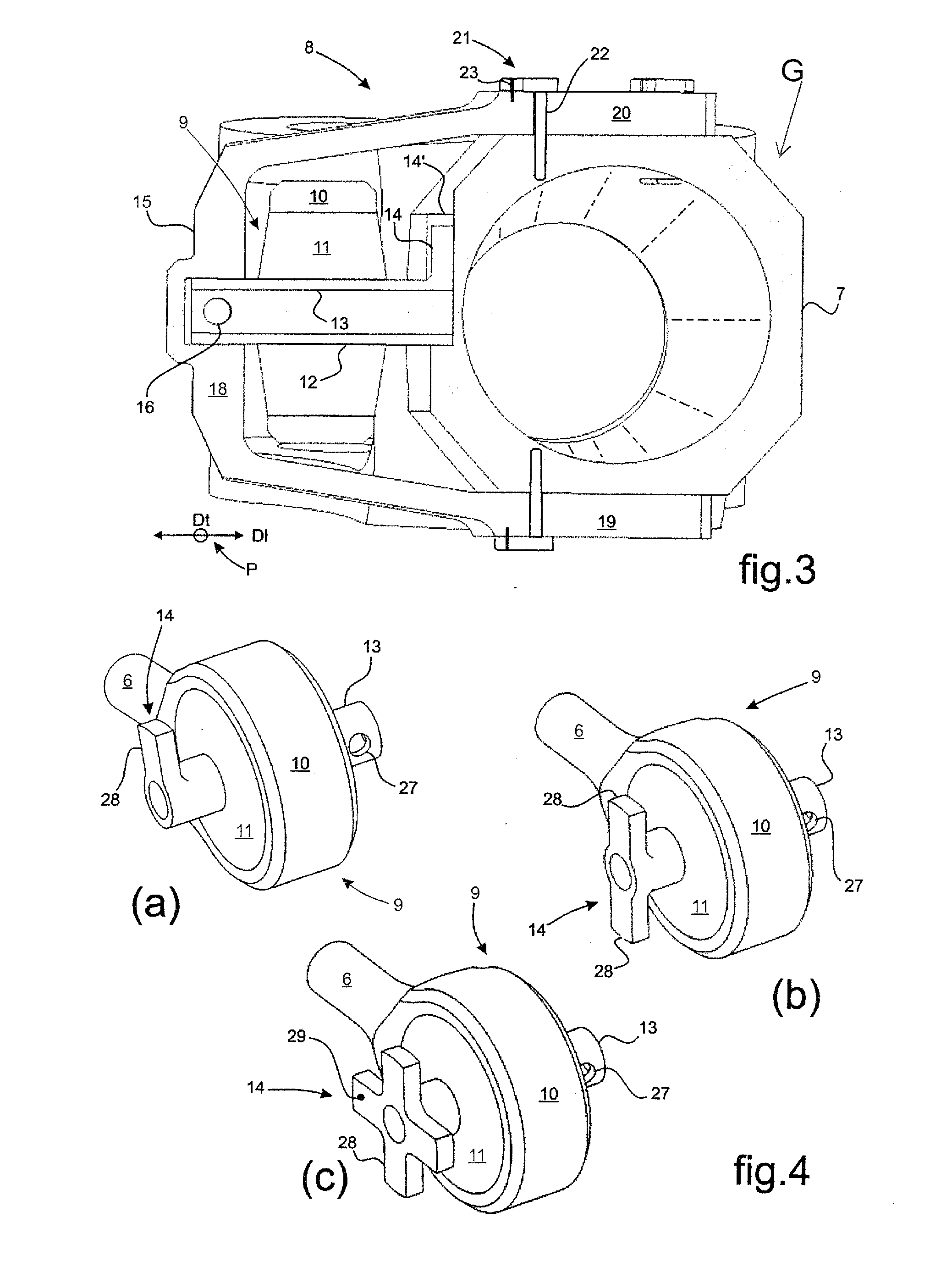
A rotorcraft rotor having each of its blades fitted with a lead / lag damper. A connection device between the blade root of a blade under consideration and a lead / lag damper comprises a rod passing through a laminated ball joint secured to a distal endpiece of the lead / lag damper. The rod extends in the general plane in which the blade extends, being prevented from moving firstly in rotation by being embedded in the blade root and secondly in translation along the general transversely-extending direction of the blade by being pinned to a U-shaped yoke fastened to the blade root.

Description

CROSS REFERENCE TO RELATED APPLICATION[0001]This application claims priority to French patent application No. FR 14 02816 filed on Dec. 11, 2014, the disclosure of which is incorporated in its entirety by reference herein.BACKGROUND OF THE INVENTION[0002](1) Field of the Invention[0003]The present invention relates to the field of rotorcraft rotors, and it relates more particularly to ways of providing lead / lag damping for the blades of such rotors.[0004]The present invention provides more specifically a rotorcraft rotor fitted with connection devices between lead / lag dampers and the blades of the rotary wing of said rotor. Such connection devices are more particularly of the type comprising a respective laminated ball joint that forms a stratified elastomer body incorporating blades of metal. Such a laminated ball joint is interposed in particular between a blade and a lead / lag damper associated therewith. This ball joint accommodates multidirectional relative movements between the...

Claims


Application Information

Patent Timeline
Patent Type & Authority Applications(United States)
IPC IPC(8): B64C27/39B64C27/51
CPCB64C27/51B64C27/39
Inventor MASSAL, FABIEN
Owner EUROCOPTER
Learn More