
Device for draining liquids for an aircraft engine

a technology for aircraft engines and liquids, which is applied in the direction of machines/engines, turbine/propulsion fuel valves, transportation and packaging, etc., can solve the problems of anomalous flow rate and insufficient delivery of pumping means for discharging liquids collected in collectors, so as to limit maintenance operations and minimise contact

Active Publication Date: 2016-10-27
SAFRAN HELICOPTER ENGINES
View PDF8 Cites 8 Cited by
  • Summary
  • Abstract
  • Description
  • Claims
  • Application Information

AI Technical Summary

Benefits of technology

The invention is a draining device for engines that collects various liquids from the engine and pumps them out. The device includes monitoring means to detect any abnormal flow rate, which may indicate a malfunction or large liquid leaks. This monitoring means helps to limit maintenance operations and minimize aircraft parts removal prematurely, reducing maintenance costs. The device does not require a return tank and can be connected to a valve to control the flow of drained liquids. The pumping means are located in the collector or connected to the collector by a conduit, making the device smaller and more efficient. The drained liquids are then combusted in the engine exhaust nozzle to minimize external pollution.

Problems solved by technology

Said flow rate is anomalous when it is greater than the delivery of the pumping means.
On the other hand, in the event of a malfunction and large liquid leaks, i.e. when there is an engine fault, the delivery of the pumping means is no longer sufficient for discharging the liquids collected in the collector.

Method used


Image

  • Device for draining liquids for an aircraft engine
  • Device for draining liquids for an aircraft engine
  • Device for draining liquids for an aircraft engine

Examples


Embodiment Construction

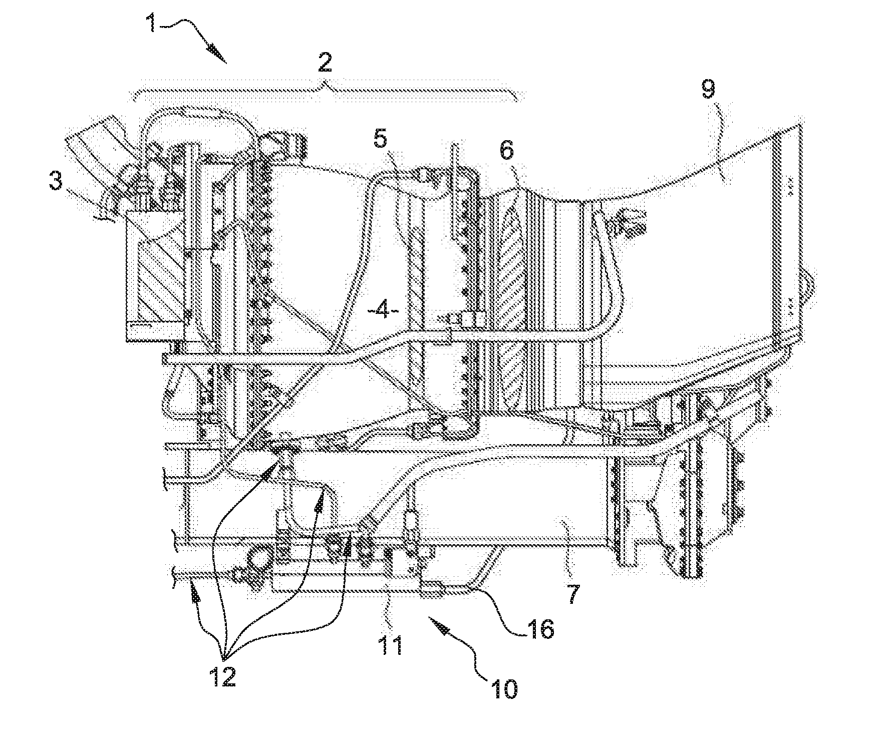
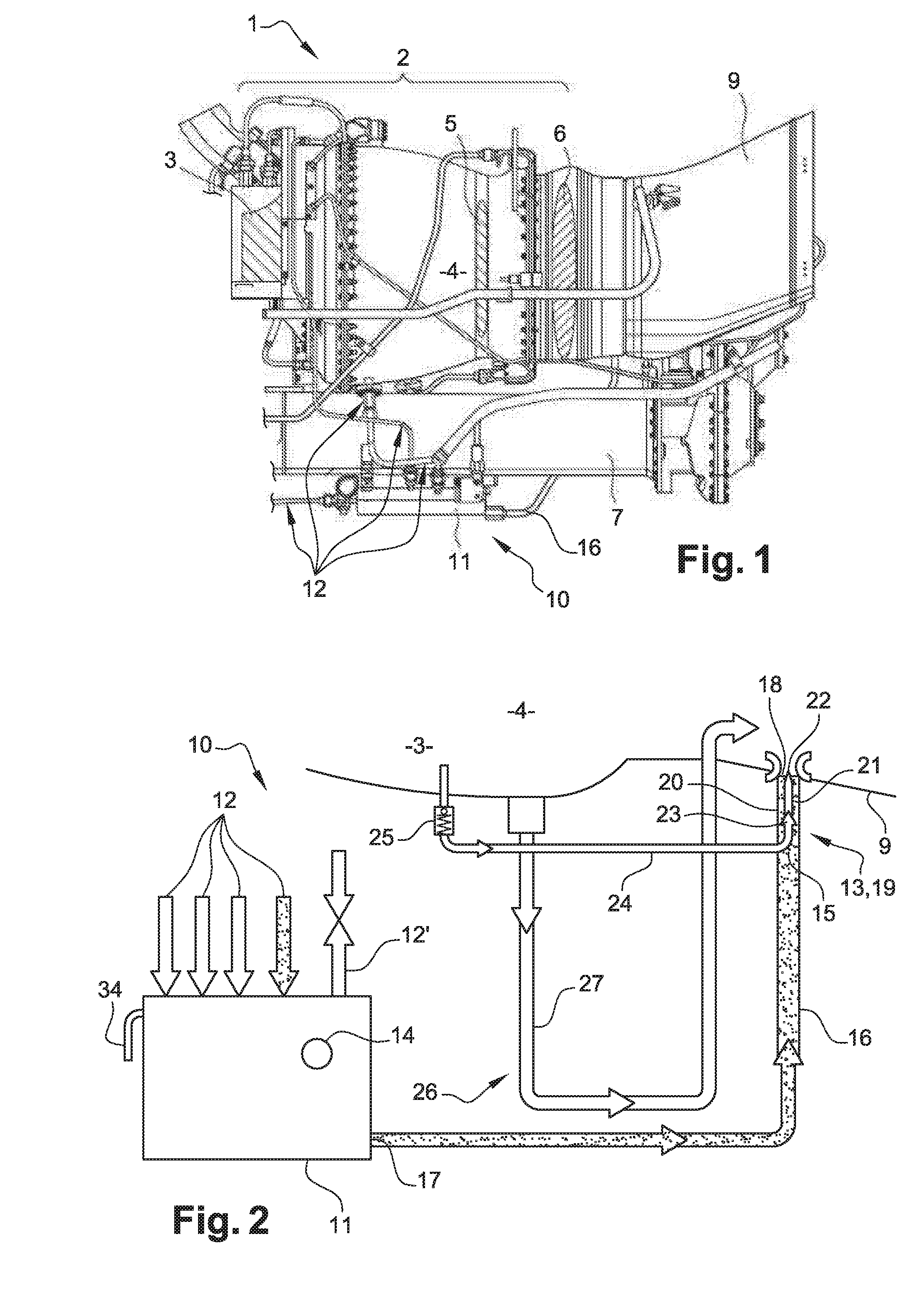
[0027]With reference to the side view in FIG. 1, an aircraft engine 1 (in this case an engine of a helicopter) comprises (seen in a cutaway view) a gas generator 2 formed by a compressor 3, by a combustion chamber 4 and by a turbine 5, which is connected to a free turbine 6. The free turbine 6 drives the main rotor (not shown) by means of a power shaft 7 via a gearbox (not shown). The gases from the combustion are ejected into an exhaust nozzle 9.

[0028]In order to make the engine clean, the engine 1 is provided with a drainage device 10 intended for collecting the residual liquids (fuel, oil, water condensates, impurities, etc.) coming from the engine.

[0029]Typically, a draining device 10 comprises a collector 11 and lines 12 for draining liquids originating from various parts of the engine, the outlets of which lines lead into the collector 11.

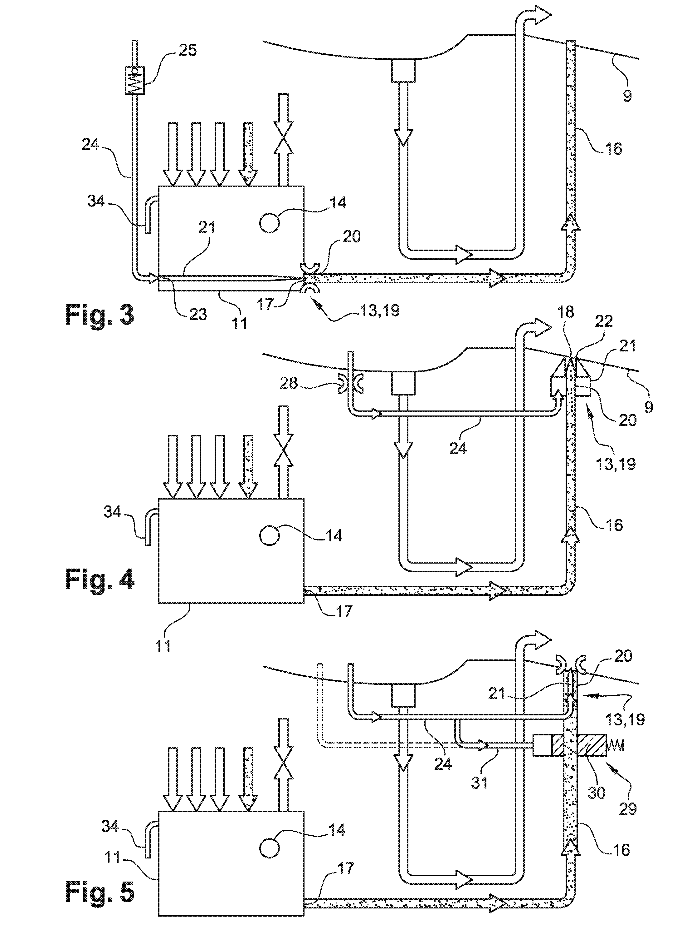
[0030]A device according to the invention for draining liquids further comprises means for pumping liquids held in the collector 11 and for ...


PUM


Abstract

Device (10) for draining liquids for an aircraft engine (1), comprising a collector (11) designed to collect liquids drained from the engine, characterised in that said device comprises means (13, 19) for pumping the liquids held in the collector and for discharging said liquids, and monitoring means (14) designed to indicate when the liquids have been collected by the collector in an anomalous manner, said monitoring means being designed to be activated when the flow rate of collected liquids is greater than the delivery of the pumping means.

Description

TECHNICAL FIELD[0001]The present invention relates to a device for draining liquids for an aircraft engine, to an aircraft engine comprising such a device, and to a method for inspecting said engine.PRIOR ART[0002]In engines for aircraft such as helicopters, it is often necessary to discharge different types of liquids, for example fuel or oil, to prevent said liquids from building up and disrupting the functioning of said engines. For example, some engines require purging operations, which cause losses of liquids (fuel, oil, etc.) that have to be recovered and treated.[0003]In the current state of the art, a return tank is provided for recovering said liquids, i.e. at least one duct is provided to convey the liquids to the aircraft fuel tank. However, this technology has several drawbacks. Indeed, the aircraft manufacturer is forced to provide said return tank used for recovering the different liquids drained from the engine. This technical constraint is exacerbated by the fact tha...

Claims


Application Information

Patent Timeline
Patent Type & Authority Applications(United States)
IPC IPC(8): F02C7/232F01M11/04B64D45/00
CPCF02C7/232B64D45/00F05D2270/80F05D2260/602F05D2220/329F01M11/0458F02C9/26F05D2260/601B64D37/26B64C1/1453
Inventor PY, JEAN-MICHEL PIERRE CLAUDEBENEZECH, PHILIPPE JEAN RENE MARIECOMBEBIAS, SEBASTIENFOUCHE, SEBASTIENHERNANDEZ, LORENZO HUACANLE BORGNE, ERICNAPIAS, LIONELQUAIREAU, MAXIMEROGER, PHILIPPEZORDAN, CEDRIC
Owner SAFRAN HELICOPTER ENGINES
Learn More