Method and device for filling a paint reservoir in an automated painting installation

a technology for automatic painting and paint reservoirs, applied in liquid handling, packaging goods types, transportation and packaging, etc., can solve the problems of loss, loss and associated cost, loss and the loss of all the paint or coating products contained in the dispensing duct of the shade changer unit, and the loss of all the paint or coating products, so as to reduce the initial investment, and reduce the loss of paint and rinsing products.

Inactive Publication Date: 2005-05-24
EISENMANN FRANCE
View PDF8 Cites 7 Cited by
  • Summary
  • Abstract
  • Description
  • Claims
  • Application Information

AI Technical Summary

Benefits of technology

[0017]The present invention aims to solve these problems, by providing a technical solution which, without modifying the machines or the robots themselves, affords a sizeable reduction in the losses of paint and of rinsing product, during changes of shade, and which also greatly limits the maintenance operations, thereby resulting in a sizeable decrease in the operating costs and in the production losses of an installation of the kind concerned, to which is added an appreciable reduction in the initial investment.

Problems solved by technology

Moreover, it will be noted that during each change of shade, all the paint or coating product, contained in the dispensing duct of the shade changer unit, is lost.
It is therefore understood that the overall loss of paint or coating product, and of cleaning product, and the associated financial cost, relating to the changes of shade, are extremely high in a given installation, this loss and the associated cost having to be multiplied by the number of sprayers, since each sprayer is assigned its own shade changing system.
To this is added a pollution problem, which stems from the wastage of paint and rinsing product which are lost as explained hereinabove.
The investment cost of such a shade changing system is, likewise, relatively sizeable, since it has to be multiplied by the number of sprayers of the installation.
To this are also added the time and the costs incurred in maintaining the shade changing systems and the costs of the loss of production.
Insofar as the number of changes of shade, and the number of sprayers, constitute unmodifiable parameters, it is apparently difficult to achieve a reduction in the losses of paint and of rinsing product, as well as a reduction in the maintenance operations, and to reduce the scale of the resulting costs and pollution.

Method used


Image

  • Method and device for filling a paint reservoir in an automated painting installation
  • Method and device for filling a paint reservoir in an automated painting installation
  • Method and device for filling a paint reservoir in an automated painting installation

Examples


Embodiment Construction

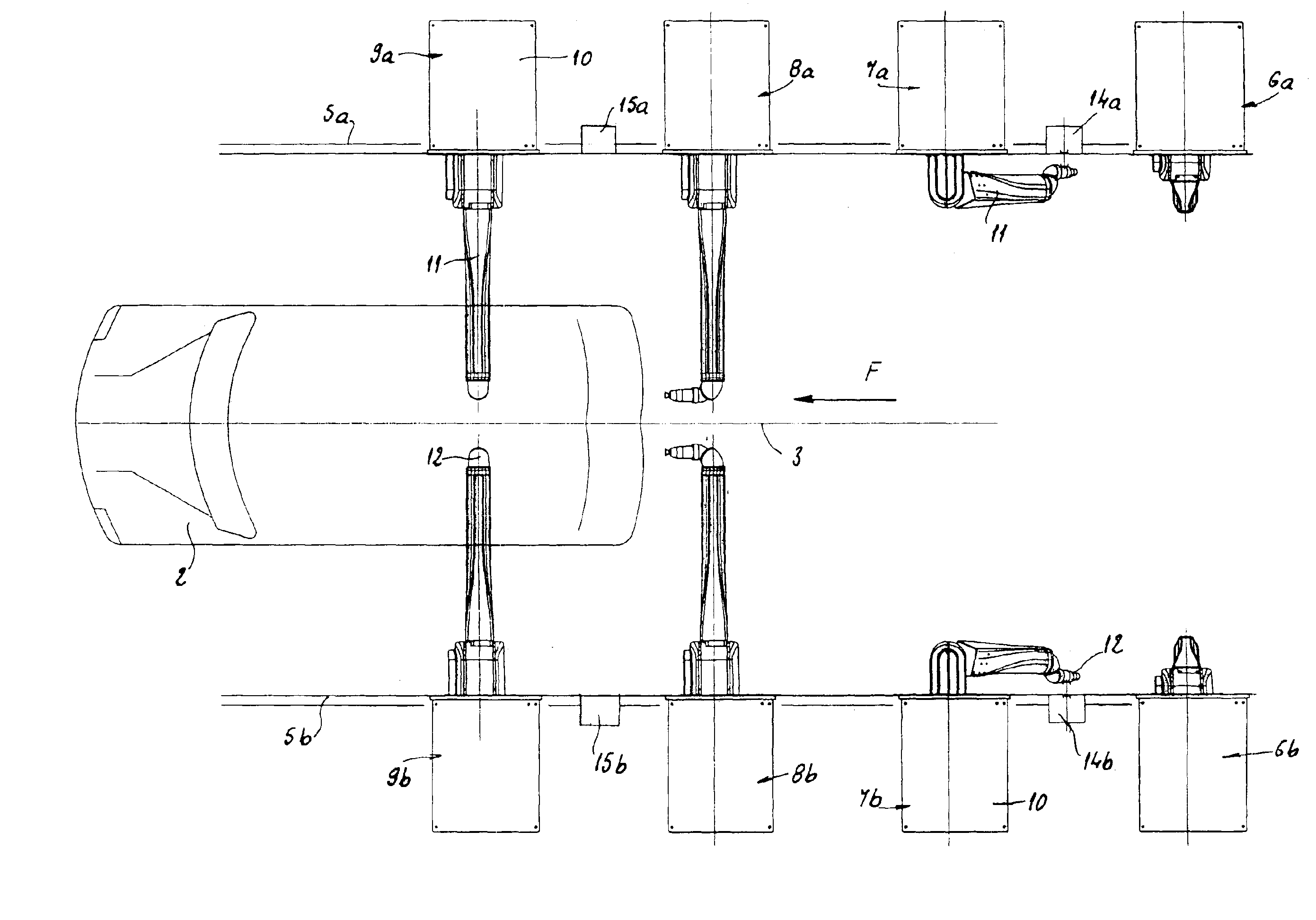
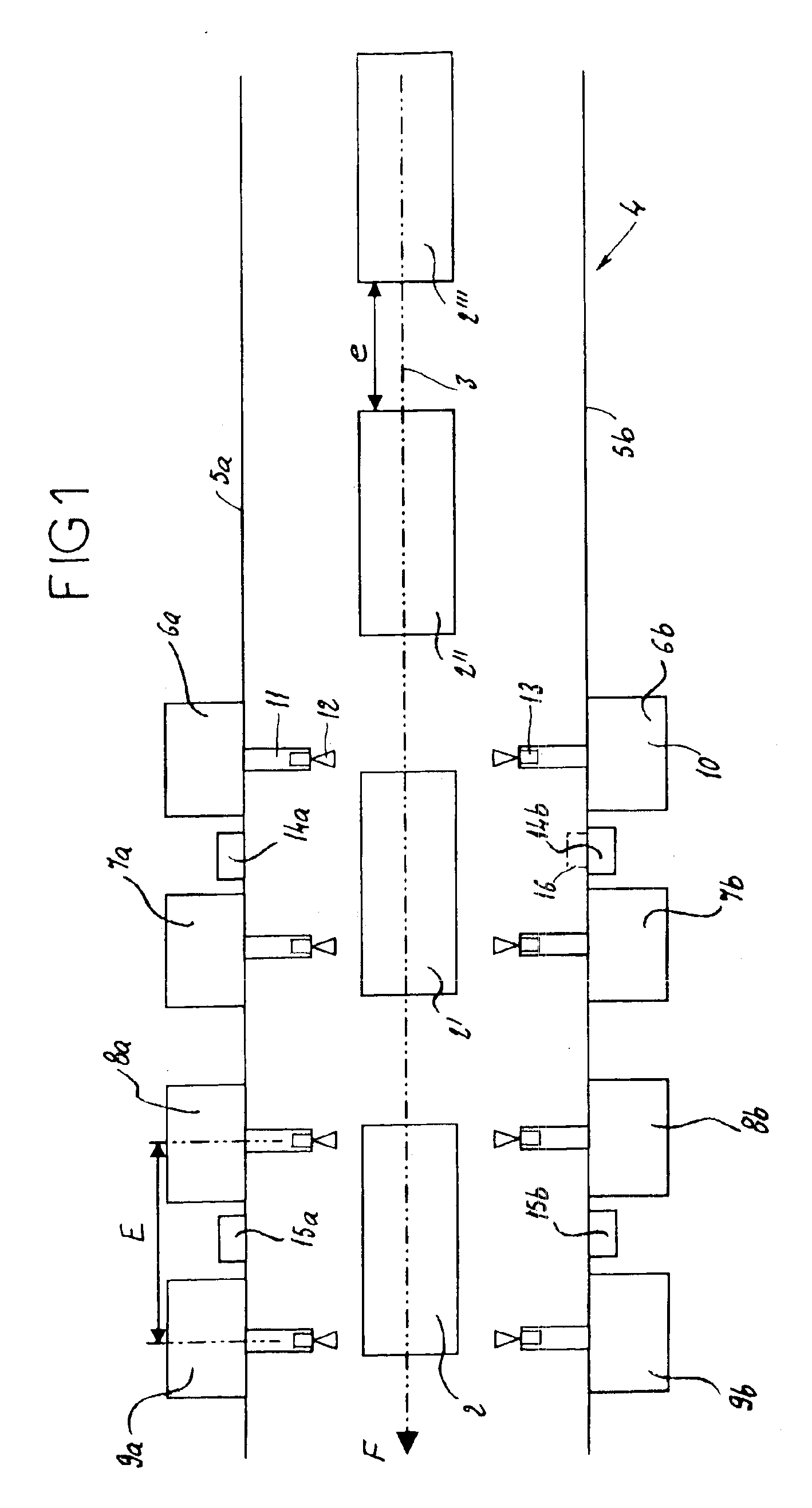
[0032]Arranged in succession on both sides of the painting booth 4 are painting machines or robots, placed facing one another, i.e. for example:[0033]on the right side of the booth 4, successive machines 6a, 7a, 8a and 9a; [0034]on the left side of the booth 4, successive machines 6b, 7b, 8b and 9b;

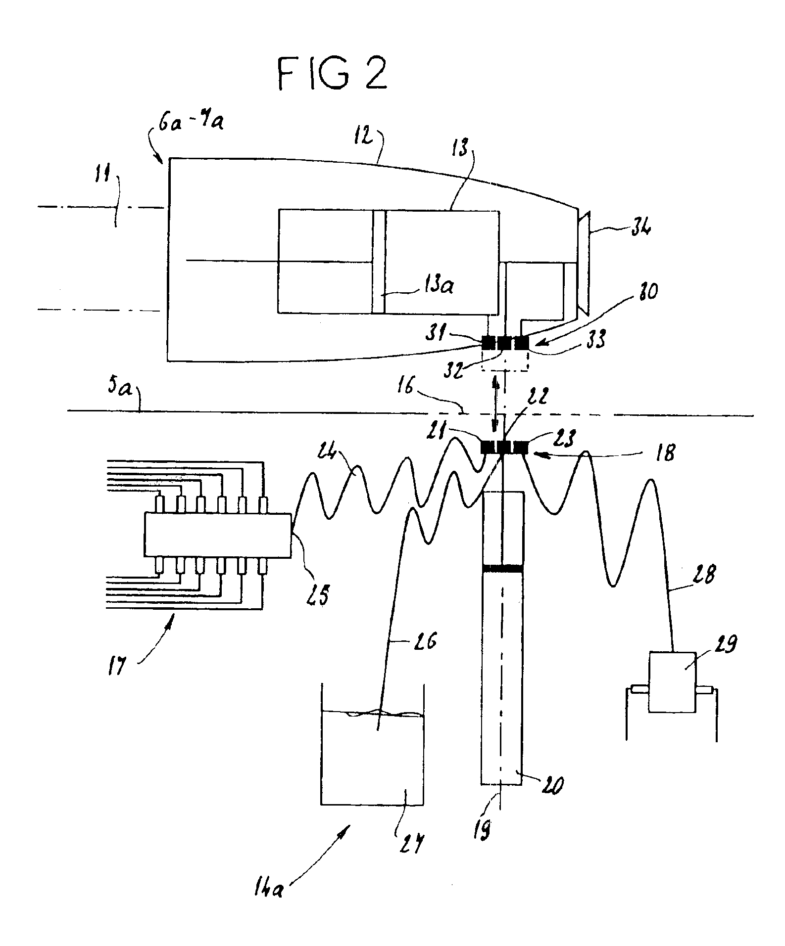
[0035]Each painting machine possesses a fixed frame 10, and a mobile arm 11 situated inside the booth 4 and carrying, at its end, a sprayer 12 with which is associated a paint reservoir 13 with piston 13a (visible in FIG. 2).

[0036]On each side of the booth 4, the machines 6a to 9a, or 6b to 9b, are spaced at intervals E, of for example between 2.5 and 3 meters.

[0037]According to the invention, all these machines are, on each side of the booth 4, associated pairwise as far as the supplying of their reservoirs 13 with paint is concerned, that is to say there is provided a dispensing system common to two consecutive machines, i.e. in detail:[0038]a dispensing system 14a common to two machin...


PUM

PropertyMeasurementUnit
colorsaaaaaaaaaa
flexibleaaaaaaaaaa
electrically conductingaaaaaaaaaa

Abstract

The invention concerns painting installations comprising painting machines or robots (6a, 6b, 7a, 7b, 8a, 8b, 9a, 9b), each with a sprayer (12) and a paint reservoir (13), associated with the sprayer and designed to supply it, the machines or robots being arranged along a painting line for motor vehicle bodies (2). Each machine or robot is provided with a fluidic connector, designed to co-operate discontinuously with a dispensing system (14a, 14b, 15a, 15b) comprising a color shade-changing unit. Each dispensing system (14a, 14b, 15a, 15b) is arranged between two consecutive machines (6a, 7a; 6b, 7b; 8a, 9a; 8b, 9b), and is common to those two machines, which are successively connected thereto to fill their respective reservoirs each time there is a color shade change.

Description

TECHNICAL FIELD OF INVENTION[0001]The present invention relates, in a general manner, to the field of automated painting installations useable in particular for applying paint and especially electrically conducting paint or other similar coating product to automobile bodies. This invention pertains, more particularly, to the filling of the paint reservoirs, in the case of installations using painting machines or robots each carrying a mobile reservoir intended for supplying a paint spray gun or cup.DESCRIPTION OF RELATED ART[0002]Known devices of this kind, such as described in the documents EP 0 274 322, EP 0 435 005 and JP 6 190 309, make it possible to rinse, then dry and subsequently fill an electrically insulated paint reservoir, placed at the end of a robot's arm and intended to supply, according to variable and controlled instantaneous flow rates, electrostatic cups or guns for spraying water-containing paint.[0003]Certain multi-axis robots for applying paint to automobile bo...

Claims


Application Information

Patent Timeline
Patent Type & Authority Patents(United States)
IPC IPC(8): B05B13/02B05B13/04B05B12/00B05D1/02B05B12/14B05D3/00B05D7/14
CPCB05B12/1463B05B13/0452B05B13/0431B05B12/14
Inventor CEBOLA, DOMINIQUEFOUVET, MICHEL
Owner EISENMANN FRANCE
Why Eureka
Try Eureka