Motion controller device

Active Publication Date: 2016-06-16
NIHON VIDEO SYST CO LTD
View PDF10 Cites 3 Cited by
  • Summary
  • Abstract
  • Description
  • Claims
  • Application Information

AI Technical Summary

Benefits of technology

[0003]It is very difficult for a single cameraperson to exactly control all of the focus, zoom, and iris positions. For this reason, in capturing images for a film, different

Problems solved by technology

It is very difficult for a single cameraperson to exac

Method used


Image

  • Motion controller device
  • Motion controller device
  • Motion controller device

Examples


Example

1. First Embodiment

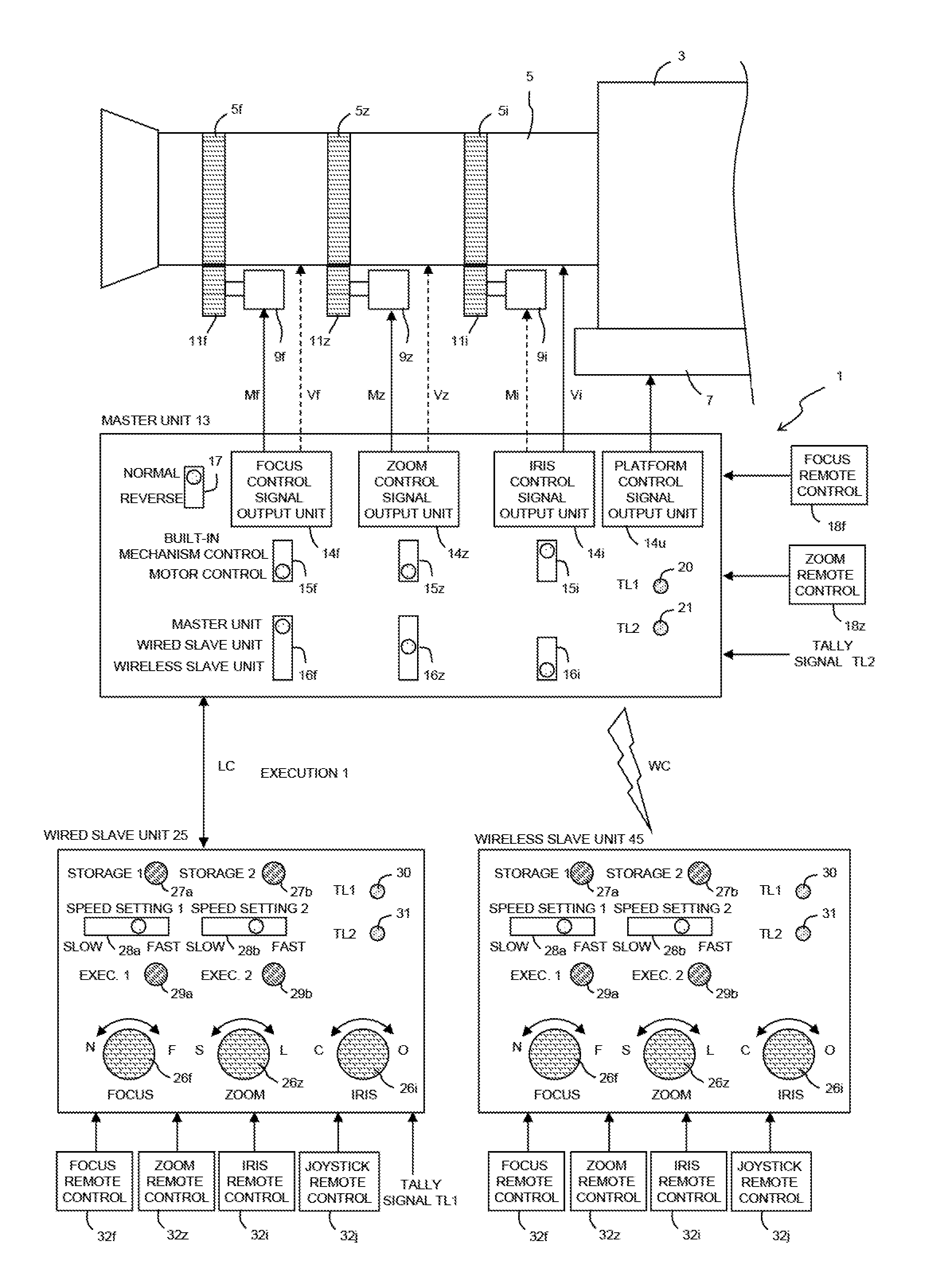
[0029]FIG. 1 shows an example configuration of a system that controls the focus, zoom, and iris positions of a lens 5 of a video camera 3 using a motion controller device 1 of a first embodiment of the present invention. The motion controller device 1 includes a master unit 13, a wired slave unit 25, and a wireless slave unit 45. The master unit 13 and wired slave unit 25 communicate with each other bi-directionally through wire communication LC, and the master unit 13 and wireless slave unit 45 communicate with each other bi-directionally through wireless communication WC. While, in the present embodiment, the wired slave unit 25 and wireless slave unit 45 have the same configuration except for the elements relating to wired or wireless communication, they may have different configurations. One of the wired slave unit 25 and wireless slave unit 45 may be omitted. Two or more wired slave units 25 or two or more wireless slave units 45 may be provided.

[0030]The len...

Example

2. Second Embodiment

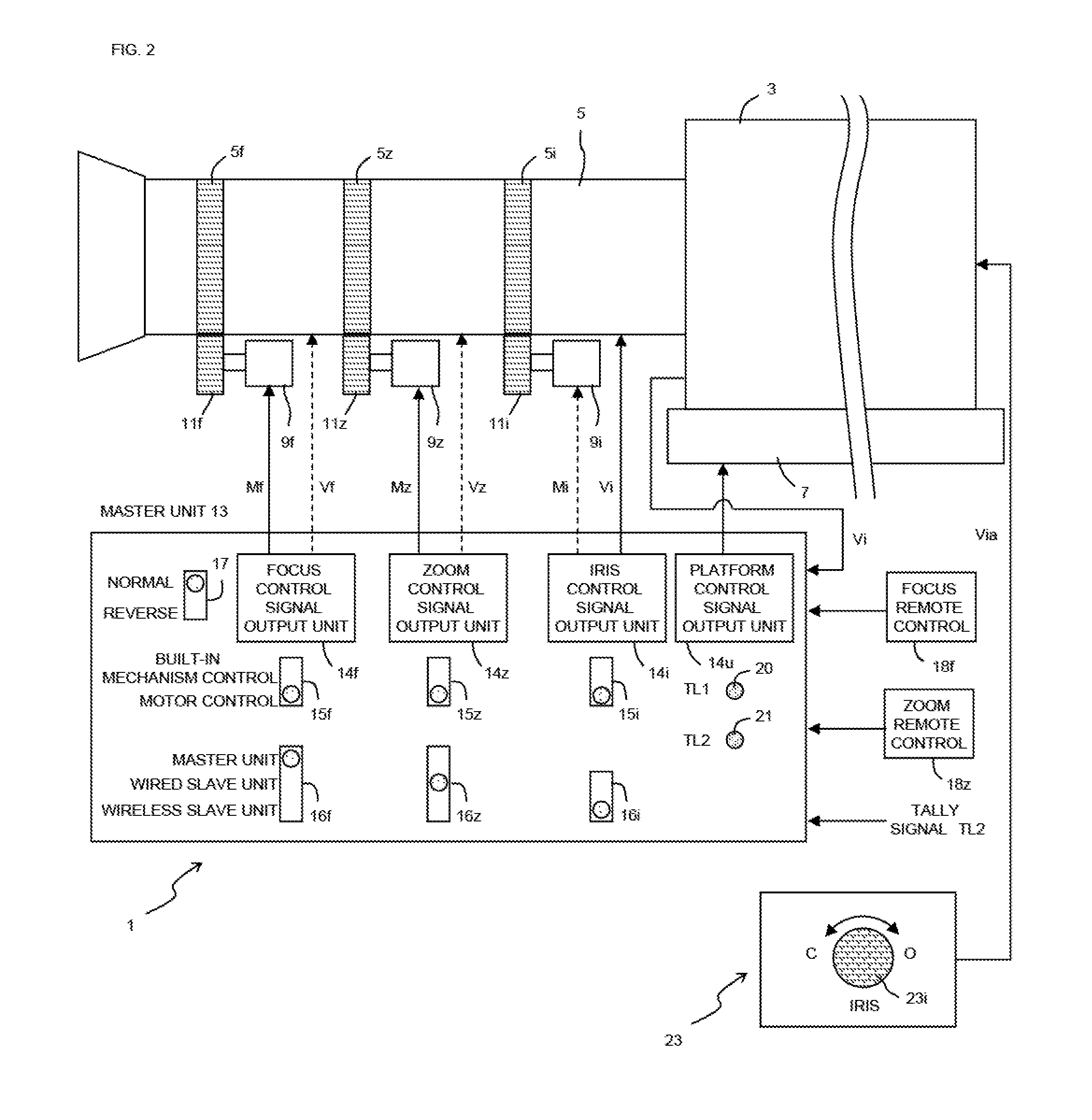
[0042]Referring now to FIG. 2, a second embodiment of the present invention will be described. Since the present embodiment is similar to the first embodiment, the differences therebetween will be mainly described.

[0043]In the present embodiment, a dedicated camera control unit (CCU) 23 is connected to a video camera 3. The CCU 23 includes an iris position control volume 23i. By operating the control volume 23i, a change is made to an iris position control CCU output signal Via. The changed CCU output signal Via is inputted to the video camera 3 and outputted therefrom as it is or after converted, as a built-in mechanism control signal Vi corresponding to the CCU output signal Via.

[0044]Typically, a lens 5 is provided with a built-in motor-driven mechanism for controlling the iris position, and when the built-in mechanism control signal Vi is inputted to the lens 5, the iris position is motor-driven controlled. However, if the lens 5 is a lens which is not provid...


PUM


Abstract

Provided is a motion controller device that allows users to easily share focus, zoom, and iris position control operations.
A motion controller device includes a master unit and one or more slave units separated from the master unit and configured to communicate with the master unit. The master unit includes a focus control signal output unit configured to output a control signal for controlling a focus position of a lens of a video camera, a zoom control signal output unit configured to output a control signal for controlling a zoom position of the lens, and an iris control signal output unit configured to output a control signal for controlling an his position of the lens. A selection can be made as to whether an output from at least one of the focus control signal output unit, the zoom control signal output unit, and the iris control signal output unit is controlled by the master unit or the one or more slave units.

Description

TECHNICAL FIELD[0001]The present invention relates to a motion controller device that can control the focus, zoom, and ins positions of a lens of a video camera.BACKGROUND ART[0002]Typically, images for a film are captured using a 2K, 4K, or 8K video camera for broadcast. Making a film having a higher degree of completion requires zoomed-in images, or various techniques for enhancing the sense of realism of the site, such as rack focus. When a director makes a high level of request to a cameraperson, the cameraperson has to satisfy the request by repeatedly capture images and precisely controlling rack focus, zoom speed, or iris-controlled image brightness.SUMMARY OF INVENTION[0003]It is very difficult for a single cameraperson to exactly control all of the focus, zoom, and iris positions. For this reason, in capturing images for a film, different persons may share the focus, zoom, and iris position adjustment operations, and there is a desire for a method for allowing different per...

Claims


Application Information

Patent Timeline
IPC IPC(8): H04N5/232H04N5/225
CPCH04N5/23206H04N5/23296H04N5/2259H04N5/222H04N23/66H04N23/67H04N23/69H04N23/75H04N23/58
Inventor HASHIGUCHI, KENTARO
Owner NIHON VIDEO SYST CO LTD
Why Eureka
Try Eureka