
Vertically oriented transportable container with improved stability

a technology of vertical orientation and transportable containers, applied in the field of vertical orientation of transportable containers with improved stability, can solve the problems of unbalanced container, less stable container, and significantly higher container of the same capacity

Active Publication Date: 2016-06-30
QUICKTHREE TECH LLC
View PDF7 Cites 47 Cited by
  • Summary
  • Abstract
  • Description
  • Claims
  • Application Information

AI Technical Summary

Benefits of technology

The patent describes a container design that results in improved stability and flexibility when handling and positioning the container. The container is cylindrical, which eliminates structural issues related to corners, and a chute assembly is included to provide increased leeway in positioning the container. Additionally, a transport trailer can load the container in multiple orientations to facilitate positioning the chute outlet at the required location, and can be detached when the container is erected.

Problems solved by technology

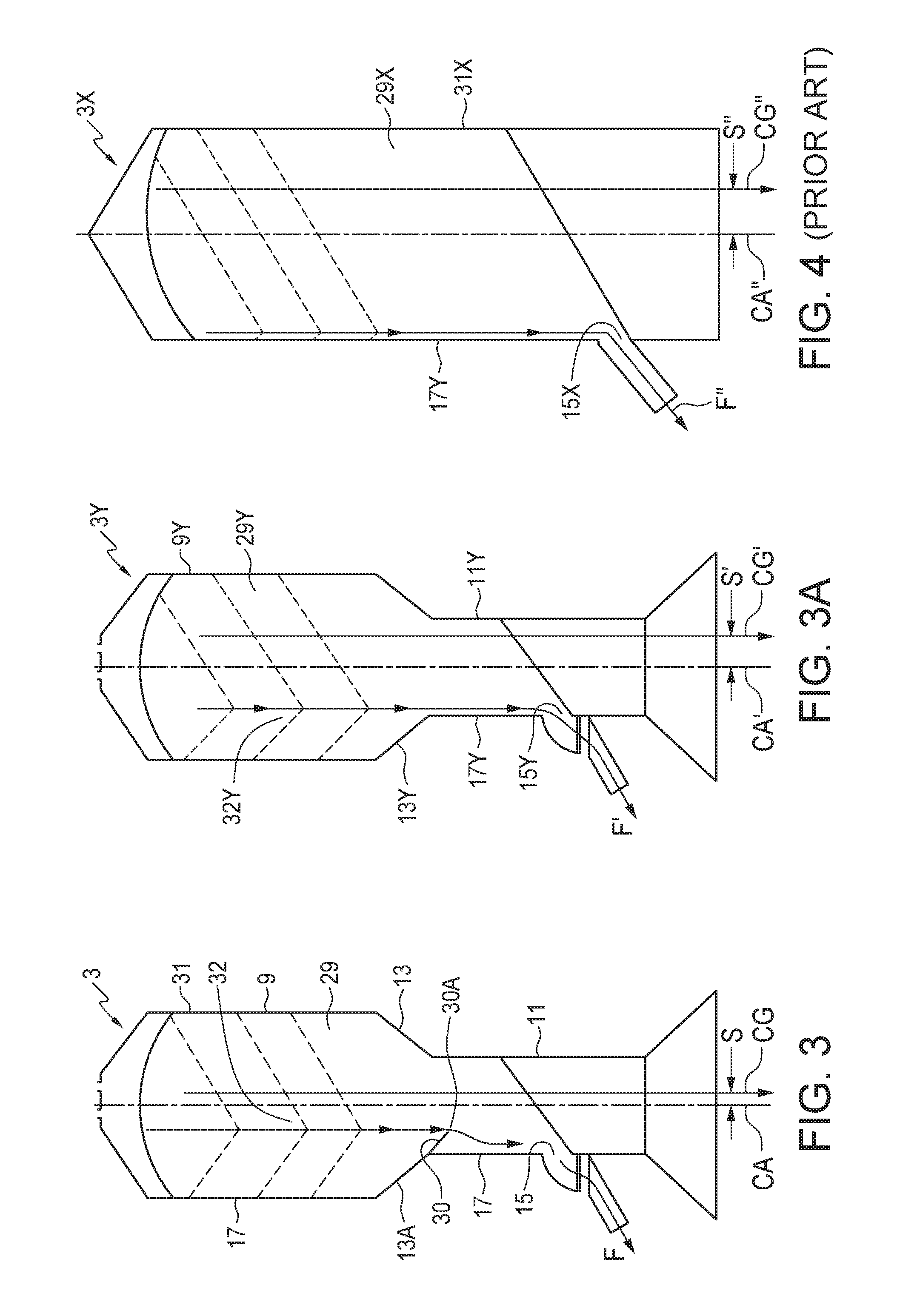
Thus the loaded container is unbalanced, with more weight on the side opposite the port, making the container less stable, as the wind force necessary to be exerted on the port side of the container to tip the container over is reduced.
Alternatively the container can be mounted on legs and a chute can receive the material and direct it to a location beside the container, however this makes containers of the same capacity considerably higher and less stable.
When filled, the weight of the contents keeps the container in place but when empty, winds or accidental contact with other equipment being moved at the work site can more easily cause the container to tip over.

Method used


Image

  • Vertically oriented transportable container with improved stability
  • Vertically oriented transportable container with improved stability
  • Vertically oriented transportable container with improved stability

Examples


Embodiment Construction

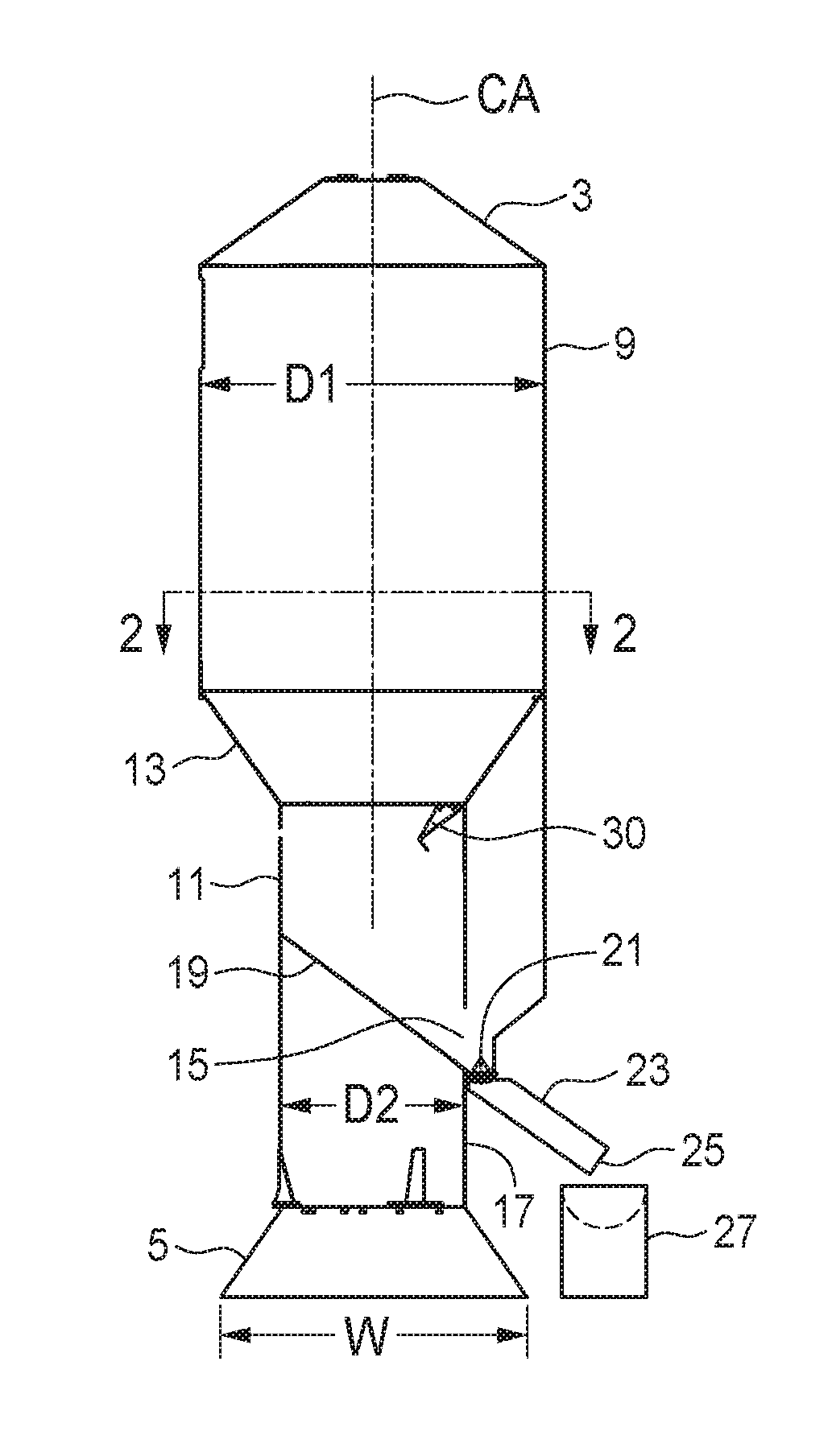
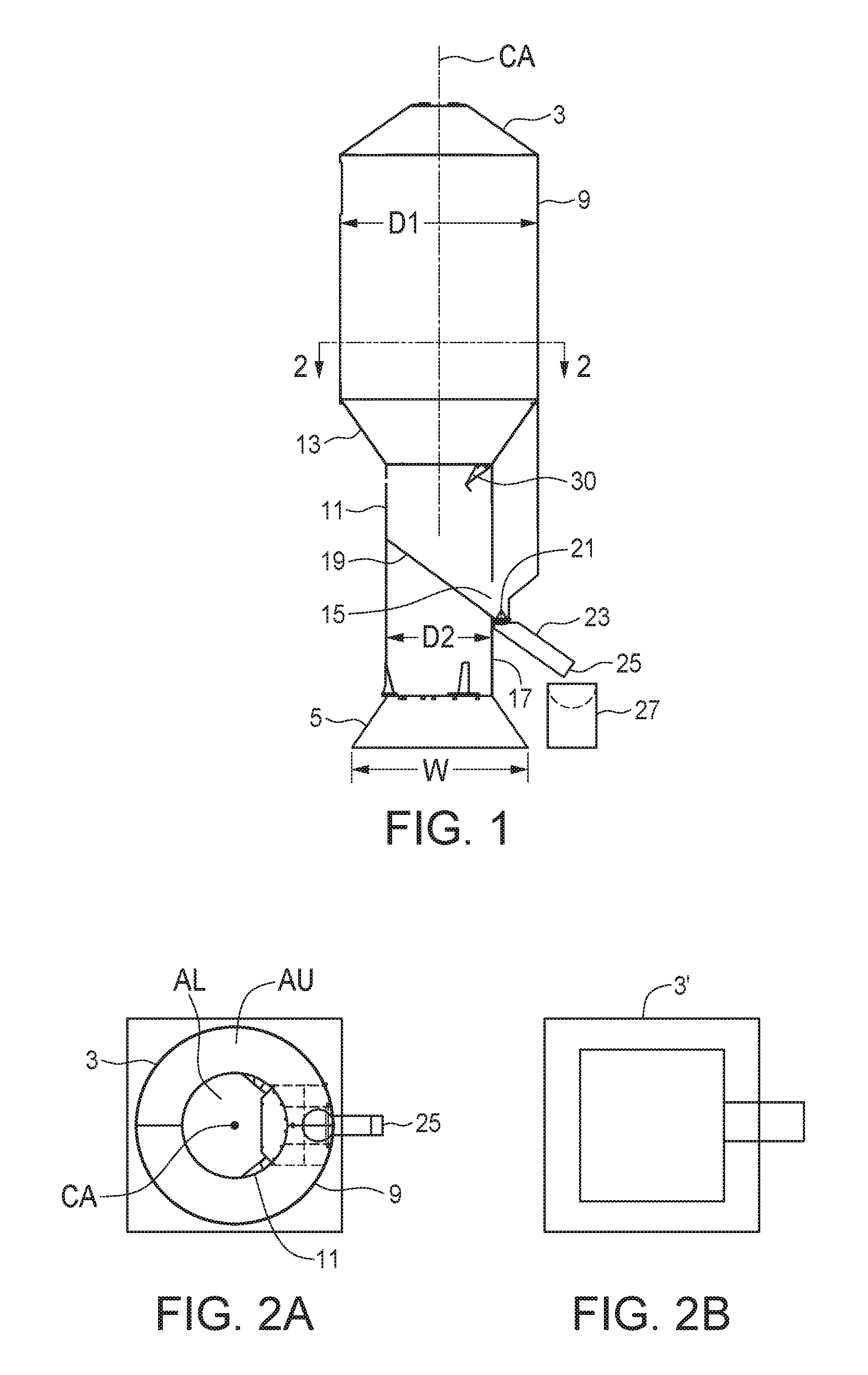
[0037]FIG. 1 schematically illustrates a cut away side view of an embodiment of a transportable container apparatus 1 of the present invention. The apparatus 1 comprises an elongate container 3 having a central axis CA, and a base 5 attached to a bottom end of the container 3. Load cells may be provided between the container 3 and base 5 to indicate how much material is in the container 3. The illustrated container 3 is cylindrical, as schematically illustrated in the sectional view FIG. 2A of the container 3, but a container for use with the present invention could also he square as schematically illustrated in the sectional view FIG. 2B of a container 3′, or another shape such as hexagonal, octagonal, or the like where the container 3 and base 5 are symmetrical about the central axis CA. It is contemplated that a cylindrical shape will best facilitate manufacture of the apparatus 1. however other shapes could also he used.

[0038]The container 3 comprises an upper container section ...


PUM


Abstract

A transportable container apparatus includes an elongate container having a central axis and a base attached to a bottom end of the container. The container and base are substantially symmetrical about the central axis and the container is oriented substantially vertically with the base resting on a ground surface when in a working position. The container having an upper container section with upper walls substantially parallel to the central axis and a lower container section with lower walls substantially parallel to the central axis. The upper container section includes a sloping hopper at a bottom thereof to direct granular material into the lower container section. A floor of the container is sloped toward an outlet port defined in a ported wall of the lower container section such that granular material stored in the container slides down the floor to the outlet port.

Description

BACKGROUND[0001]This invention is in the field of transportable containers such as bins, tanks, or the like, and in particular such containers that are vertically oriented when installed at a work site and where stability is improved.[0002]In many industries it is required to set up an array of equipment at a temporary work site, and then disassemble the installation, move it to another work site, and re-assemble it. For example asphalt and concrete plants are often set up in locations where large quantities of material are required for mad or building construction. Similarly well drilling rigs, such as those drilling for oil and gas, are set up at a drilling location, then taken down and moved to a different drilling location.[0003]These portable plants and rigs typically include various tanks, bins, silos, and like containers for water, asphalt, sand, cement, and other materials such as might be required at any particular work site. These are transported to the work site, commonly...

Claims


Application Information

Patent Timeline
IPC IPC(8): B65D88/28B65D88/54
CPCB65D88/542B65D88/28B60P1/04B60P3/40B65D25/42B65D88/30B65D88/32B65D88/54B65D90/582B65D90/66B65D2590/664G01F11/261G01F11/263G01G13/06G01G13/18
Inventor HERMAN, ALVINHERMAN, ERIN
Owner QUICKTHREE TECH LLC
Learn More