Replaceable atomizing unit, atomizer and electronic cigarette having same

Active Publication Date: 2016-07-07
SHENZHEN FIRST UNION TECH CO LTD
View PDF31 Cites 73 Cited by
  • Summary
  • Abstract
  • Description
  • Claims
  • Application Information

AI Technical Summary

Problems solved by technology

However, when the liquid conducting body is a ceramic rod,

Method used


Image

  • Replaceable atomizing unit, atomizer and electronic cigarette having same
  • Replaceable atomizing unit, atomizer and electronic cigarette having same
  • Replaceable atomizing unit, atomizer and electronic cigarette having same

Examples


first embodiment

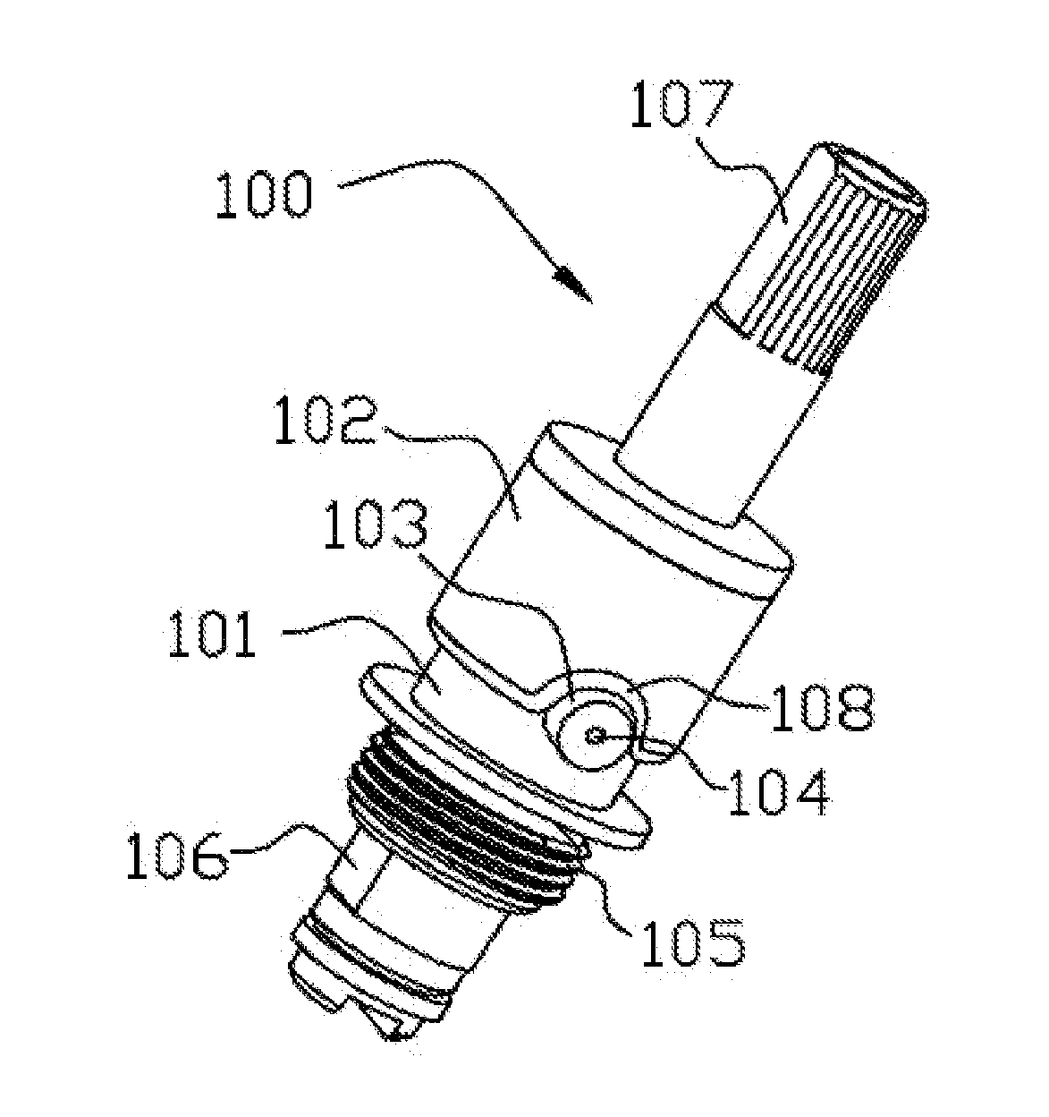
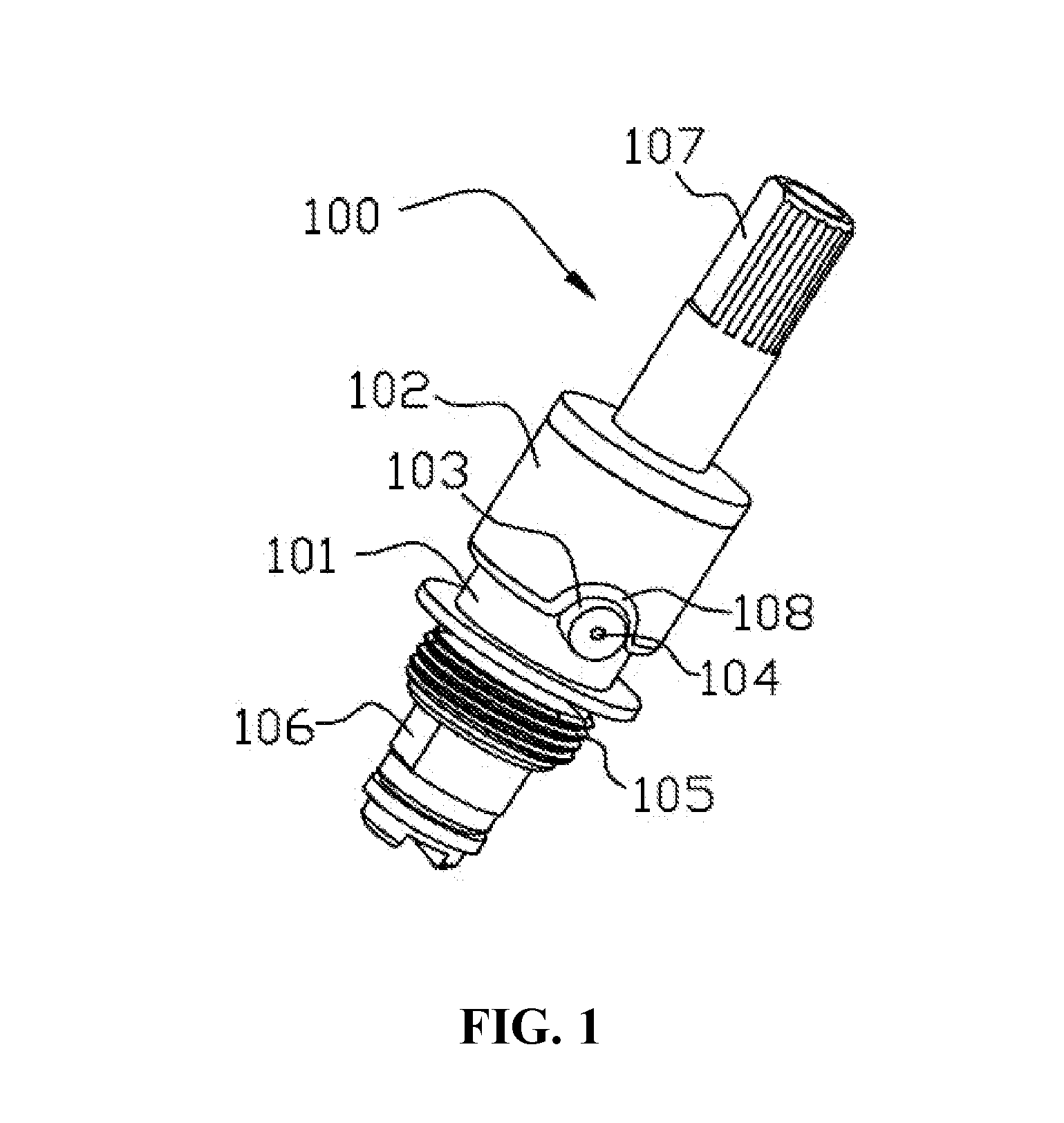
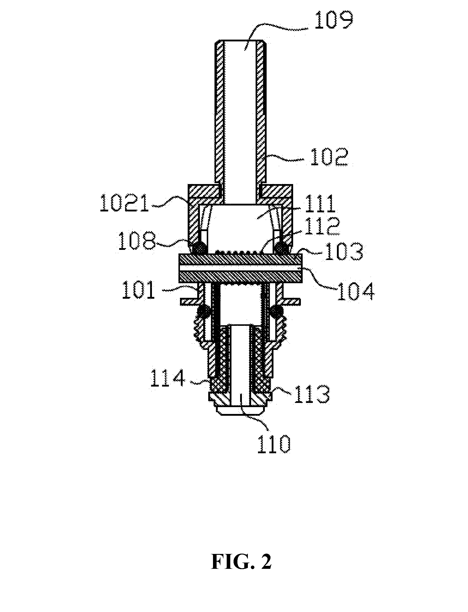
[0023]Referring to FIGS. 1-3, a replaceable atomizing unit 100 includes a liquid conducting body 103, a heating element 112 and a holder 101. The liquid conducting body 103 is configured (i.e., structured and arranged) for absorbing tobacco liquid. The heating element 112 is in contact with the liquid conducting body 103, and configured for heating the tobacco liquid to form aerosol. The holder 101 is adapted for supporting the liquid conducting body 103. The holder 101 includes an open end 1011, and a press fit element 102 is coupled with the open end 1011. In the present embodiment, the holder 101 and the press fit element 102 are both substantially cylindrical, and cooperatively form an atomizing chamber 111 after engagement. The heating element 112 is arranged in the atomizing chamber 111. The liquid conducting body 103 is supported by the holder 101, and at least part of the liquid conducting body 103 extends outside of the atomizing chamber 111.

[0024]A resilient component nest...

second embodiment

[0031]Referring to FIGS. 5-6, another atomizing unit 200 is provided. The atomizing unit 200 is similar to the atomizing unit 100, except for a sum total of the liquid conducting bodies and a structure of the resilient component.

[0032]The atomizing unit 200 includes a holder 201, and a press fit element coupled to the holder 201. The holder 201 includes an open end 2011 at an end. The open end 2011 defines gaps 2012 for receiving liquid conducting bodies in a sidewall. A metallic tube 208 is provided at an opposite end of the holder 201. The metallic tube 208 serves as an electrode. An insulated ring 209 is arranged between the metallic tube 208 and the holder 201. The holder 201 further includes a plurality of external screws 210. Liquid conducting bodies 205, 204 are arranged in a parallel manner in the gaps 2012. The liquid conducting bodies 205, 204 are both porous ceramic rods. A heating element 207 is provided on the liquid conducting bodies 205, 204. A resilient component is ...

third embodiment

[0035]Referring to FIGS. 8-9, an atomizer 300 includes a housing 301, an atomizing unit 200 received in the housing 301, and a liquid chamber 307 received in the housing 301. A mouthpiece 303 is arranged at an end of the housing 301, and the mouthpiece 303 communicates with the atomizing chamber 206 in the atomizing unit 200. An assembling holder 302 is provided at an opposite end of the housing 301. The atomizing unit 200 is detachably connected with the assembling holder 302. Two opposite ends of the liquid conducting bodies 204, 205 extend into the liquid chamber 307. The assembling holder 302 includes a plurality of screw threads 306 configured for connecting with a power supply at a bottom part.

[0036]Referring to FIG. 9, the housing 301 includes a sleeve tube 3011, a top cover 3012 and a bottom cover 3013 arranged at two opposite ends of the sleeve tube 3011. The housing 301 further includes a transparent tube 308 inside. The liquid chamber 307 is defined in the transparent tub...


PUM


Abstract

An exemplary replaceable atomizing unit includes a liquid conducting body, a heating element in contact with the liquid conducting body, a holder, and a press fit element. The holder is configured for supporting the liquid conducting body. The holder includes an open end. The press fit element is coupled with the open end. The press fit element and the holder cooperatively define an atomizing chamber. The heating element is received in the atomizing chamber. The open end defines a gap for accommodating the liquid conducting body. At least one part of the liquid conducting body extends along the gap outside of the atomizing chamber. The atomizing unit further includes a resilient component nesting the open end, and the resilient component is tightly pressed against the liquid conducting body by the press fit element.

Description

TECHNICAL FIELD[0001]The present invention relates to electronic cigarettes, and particularly to a replaceable atomizing unit, an atomizer and an electronic cigarette using same.BACKGROUND ART[0002]A typical electronic cigarette includes a housing, a liquid chamber defined in the housing, and a replaceable atomizing unit. The atomizing unit is configured (i.e., structured and arranged) for absorbing tobacco liquid from the liquid chamber, and generating aerosol. The replaceable atomizing unit includes a liquid conducting body for absorbing tobacco liquid, a heating element, a holder, and a press fit element. The press fit element is coupled with the holder to fix the liquid conducting body.[0003]Generally, the liquid conducting body is a glass fiber core or a ceramic rod, and the holder and the press fit element are made of metal. However, when the liquid conducting body is a ceramic rod, the ceramic rod may be crushed during assembling process.[0004]What is needed, therefore, is a ...

Claims


Application Information

Patent Timeline
IPC IPC(8): A24F47/00H05B3/00A24F40/10A24F40/40
CPCH05B3/00A24F47/008A24F40/10A24F40/40
Inventor LI, YONGHAIXU, ZHONGLIHU, SHUYUN
Owner SHENZHEN FIRST UNION TECH CO LTD
Why Eureka
Try Eureka