Supercharge Your Innovation With Domain-Expert AI Agents!

Method for determining the fouling ratio of at least one filter of a ventilation system and associated ventilation system

Inactive Publication Date: 2016-07-21
ALDES AERAULIQUE
View PDF7 Cites 20 Cited by
  • Summary
  • Abstract
  • Description
  • Claims
  • Application Information

AI Technical Summary

Benefits of technology

The invention is a system that can track the amount of dust collected by filters in a ventilation system. This allows for timely replacement of the filters to prevent clogging and minimize downtime. The system also provides a visual display for easy visual tracking and alerts the user when it is time to replace the filter. Overall, the invention reduces the risk of filters becoming clogged, improves efficiency, and saves time.

Problems solved by technology

When the pressure increases and reaches a predetermined threshold, the filter is considered fouled.
The advantage of this solution lies in the fact that the fouling information may be immediately transmitted, however this solution does not allow anticipating the maintenance operations.
However, this solution does not enable knowing the fouling state of the filter in a genuine way.
Thus, the error message may occur even though the filter is not fouled or after that said filter has become fouled.

Method used


Image

  • Method for determining the fouling ratio of at least one filter of a ventilation system and associated ventilation system
  • Method for determining the fouling ratio of at least one filter of a ventilation system and associated ventilation system
  • Method for determining the fouling ratio of at least one filter of a ventilation system and associated ventilation system

Examples


second embodiment

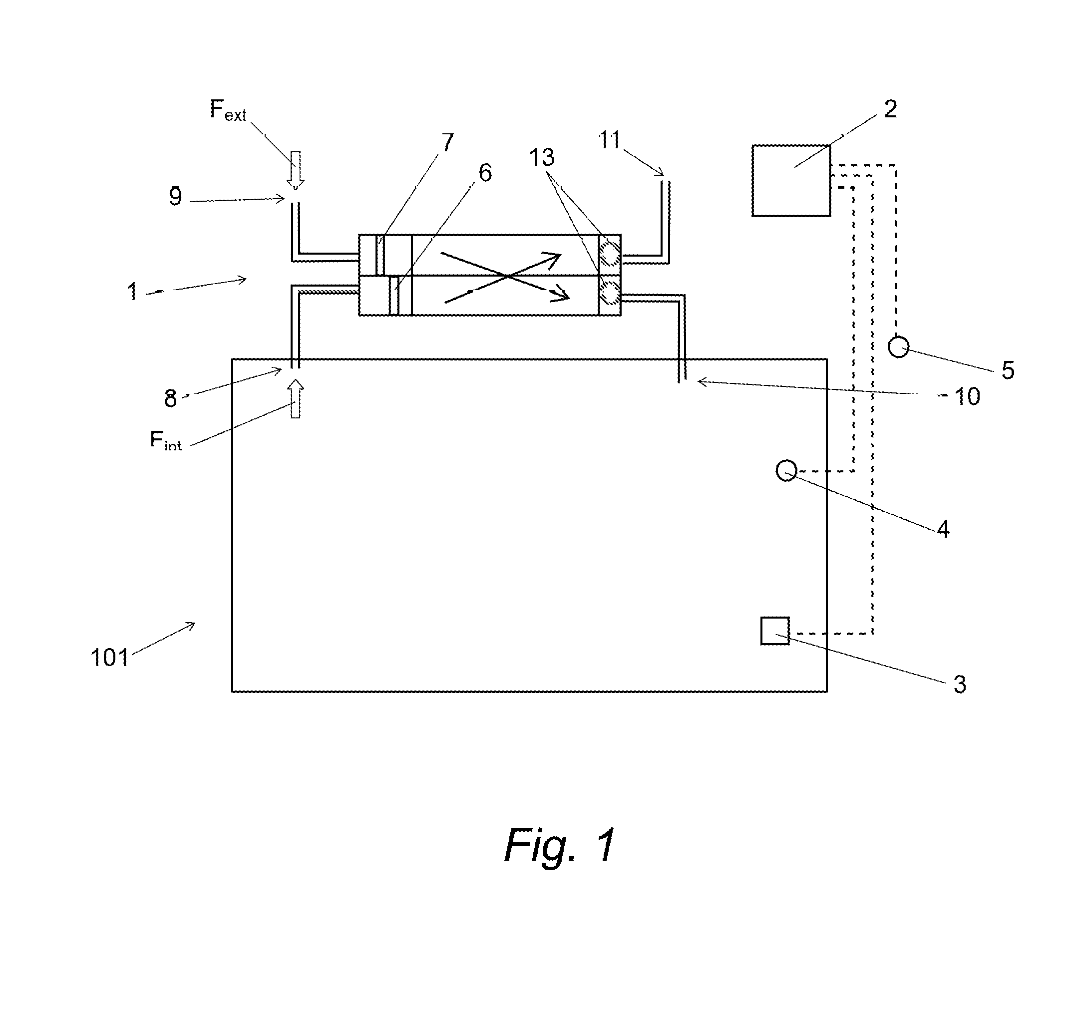
[0068]In the second embodiment, each room 101 comprises an extraction outlet corresponding to an indoor entering air inlet 8 at which an entering air filter 6 is positioned. The ventilation system 1 further comprises an indoor pollution sensor 4 by room 101. The ventilation system 1 also comprises a control unit of the fouling ratio 2 cooperating with each indoor pollution sensor 4 in order to determine the fouling ratio of each indoor entering air filter 6. Furthermore, the ventilation system 1 comprises a regulating member 12 for each indoor entering air inlet 8. Each regulating member 12 is equipped with a flow meter.

first embodiment

[0069]The determination of the fouling ratio of an indoor entering air filter 6 is carried out as described in the By using the indoor pollution data of the pollution sensor 4 of the room 101 in which is located the filter 6 and the air flow rate data measured by the regulating member 12 of the associated room 101.

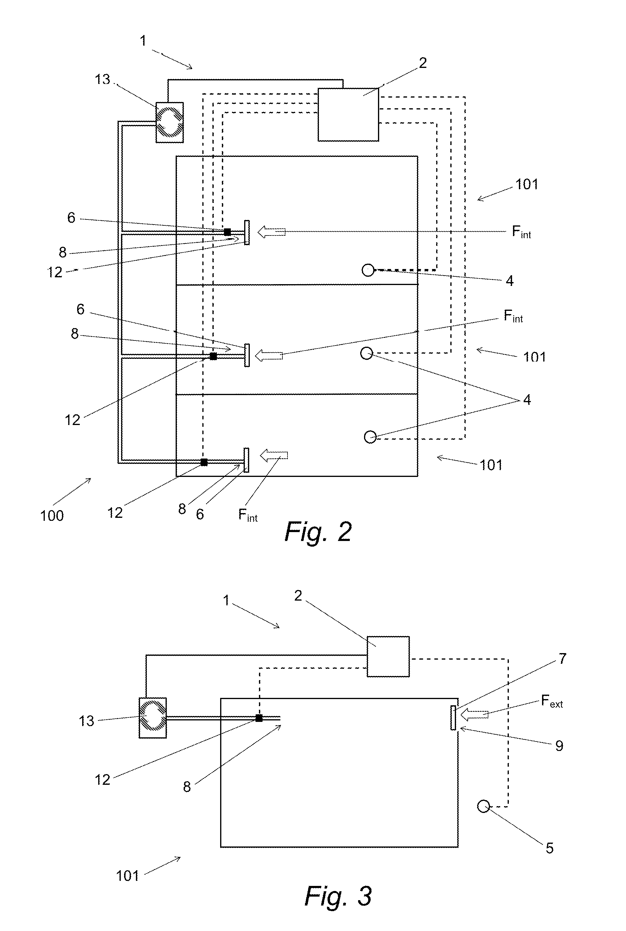
[0070]The third embodiment of the ventilation system 1 is shown in FIG. 3. In the third embodiment, the ventilation system 1 is a single flow system for a room 101 of a building 100. This embodiment may also be used for collective housing units as well as for individual housing units.

third embodiment

[0071]In the third embodiment, the room 101 comprises an extraction outlet corresponding to an outdoor entering air inlet 9 at which an entering air filter 7 is positioned. The ventilation system 1 further comprises an outdoor pollution sensor 5. The ventilation system 1 also comprises a control unit of the fouling ratio 2 cooperating with the outdoor pollution sensor 5 in order to determine the fouling ratio of the outdoor entering air filter 7. Furthermore, the ventilation system 1 comprises a regulating member 12 for the extraction outlet 8. The regulating member 12 is equipped with a flow meter.

[0072]The determination of the fouling ratio of an outdoor entering air filter 7 is carried out as described in the first embodiment. By using the outdoor pollution data of the outdoor pollution sensor 5 of the room 101 in which is located the filter 7 and the air flow rate data measured by the regulating member 12 of the room 101 or by an information feedback from the fan 13.

[0073]As an ...


PUM

PropertyMeasurementUnit
Flow rateaaaaaaaaaa
Ratioaaaaaaaaaa

Abstract

The invention concerns a method for determining the fouling ratio of at least one filter of a ventilation and / or air handling system(s) comprising the following steps:A. Selecting at least one filter to be analyzedB. Determining the theoretical filtration capacity of the filter selected in step A, depending on the theoretical efficiency of the filter and the maximum amount of dust which can be theoretically retained by the filter.C. Collecting pollution data of at least one air entering the ventilation system and passing through the selected filter,D. Measuring the air flow rate entering the ventilation system,E. Calculating the amount of dust retained by the at least one filter selected, from the pollution data of the entering air of step C and from the measurement of the entering air flow rate of step D,F. Repeating step E for each time step t.G. Determining the accumulated dust amount retained by the selected filter from the results of steps E and F.H. Determining the fouling ratio of the selected filter by comparing the accumulated dust amount determined at step G with the theoretical capacity of the filter determined in step B.

Description

TECHNICAL FIELD[0001]The present invention concerns the field of ventilation systems for buildings and more particularly the ventilation systems equipped with air filters.BACKGROUND[0002]Conventionally, buildings are ventilated for the issues of conservation of the assembly and discharge of pollutions, pollutions being in particular generated by the occupants, the equipment and the machinery present in the building and the materials of the assembly.[0003]The principle of the ventilation consists in creating an exchange of the air by displacement in an enclosed place. In this case, the ventilation of a building consists in exchanging the indoor air by bringing outdoor air and / or by recycling the indoor air.[0004]In the present application, the outdoor air means the air coming from outside the building. Furthermore, the indoor air means the ambient air present in the building.[0005]The exchange air called entering air is generally filtered to ensure a good quality of the air in the bu...

Claims


Application Information

Patent Timeline
IPC IPC(8): G01N15/08B01D46/00
CPCG01N15/0826G01N2015/084B01D46/0086F24F2110/00F24F11/30F24F11/0001F24F11/32F24F11/39F24F2110/30F24F11/52
Inventor BUSEYNE, SERGELABAUME, DAMIEN
Owner ALDES AERAULIQUE
Features
  • R&D
  • Intellectual Property
  • Life Sciences
  • Materials
  • Tech Scout
  • Unparalleled Data Quality
  • Higher Quality Content
  • 60% Fewer Hallucinations
Learn More