
Upwardly venting ridge vent and method of using same

a ridge vent and upward venting technology, which is applied in the direction of roof covering ventilation, heating types, building components, etc., can solve the problems of compressing the height of the vent and compromising the net free air flow area, and breaking up the otherwise clean lines of the shingled roof. , to achieve the effect of less effort, avoiding compression compromising issues, and being easy to install

Inactive Publication Date: 2016-07-28
CANPLAS INDS
View PDF7 Cites 4 Cited by
  • Summary
  • Abstract
  • Description
  • Claims
  • Application Information

AI Technical Summary

Benefits of technology

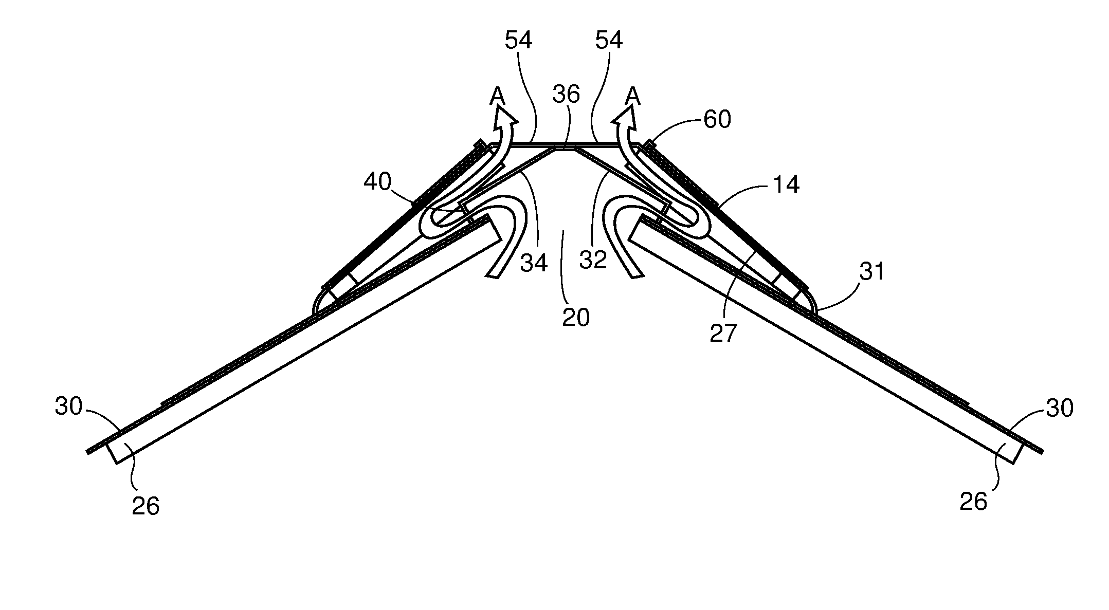
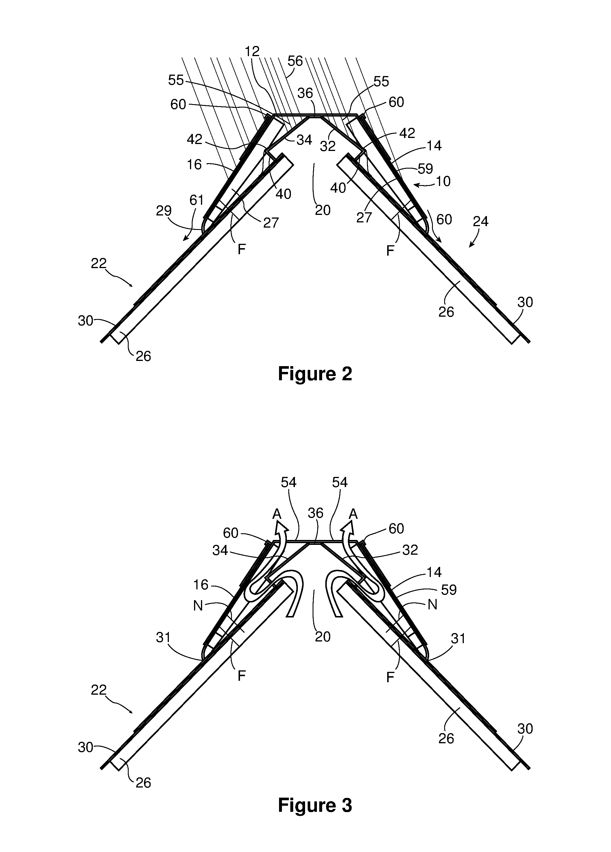
The present invention provides a ridge vent that can be easier to install than traditional designs. It includes an air flow passageway that is not located beneath any nailing points, which prevents compression issues. The fastening location allows for the use of standard length roofing nails. The ridge vent also has a centrally located upwardly facing grill that allows air to pass out of the vent and avoids the continuous side edge vents of the prior art. The vent can be easily secured to the sloped roof deck on either side of the peak adjacent to the ridge opening, using nails or the like. Opposed weather deflecting baffles may also be provided to prevent weather from passing through the grill and into the ridge opening. The baffles extend far enough to cause water or other precipitation to be shed from the baffle onto the shingled roof deck at a location spaced sideways from and below the ridge opening in the roof peak to prevent the water from passing through the open peak slot. The flexible side flanges extend well beyond the ends of the baffles and the fasteners used to secure the ridge vent in place to the roof deck pass only through the flexible side flanges into the roof deck and not through the baffles. The ridge vent can be made from a bendable material such as plastic or sheet metal and can be used on a wide variety of roof pitches without requiring any special changes or adaptations.

Problems solved by technology

However, it can be time consuming and laborious to install the row of cap shingles and again a risk arises that the act of attaching the shingles with roofing nails through the vent body will compress the height of the vent and compromise the net free air flow area.
Another issue limiting NFA in prior art is the height of the product which is limited by the length of the nails used to install.
Another problem with such prior vent designs is that the side vent openings are presented along the sides of the ridge and thus are visible when looking up parallel to the roof slope.
Such openings can break up the otherwise clean lines of the shingled roof.

Method used


Image

  • Upwardly venting ridge vent and method of using same
  • Upwardly venting ridge vent and method of using same
  • Upwardly venting ridge vent and method of using same

Examples


Embodiment Construction

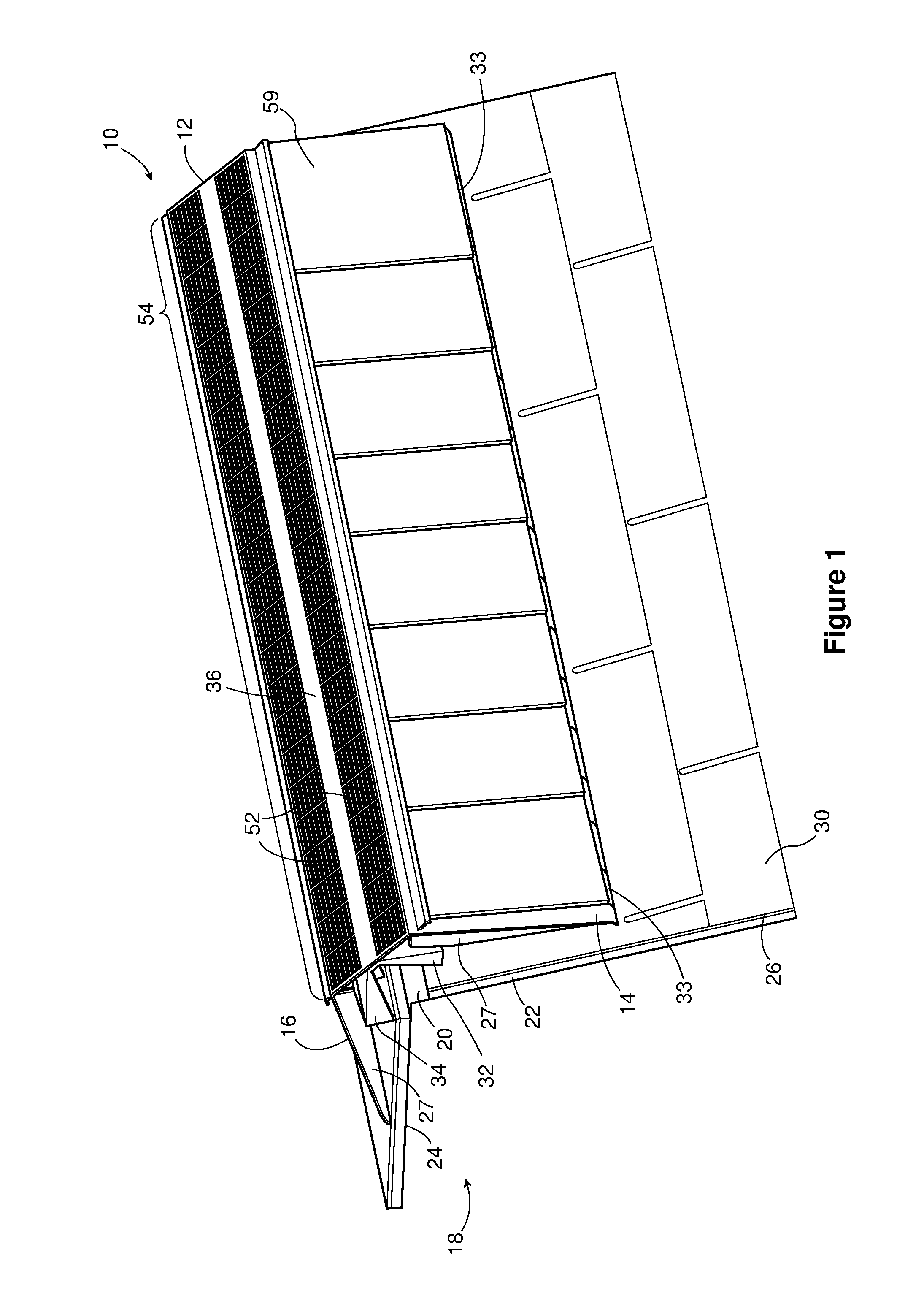
[0037]FIG. 1 shows a vent 10 according to the present invention. The vent 10 includes top surface 12, and side or outer attachment flanges 14 and 16. Also shown is a roof peak 18, with a ventilation slot 20 and sloping roof sections 22 and 24. The vent 10 may straddle the ventilation slot 20 as shown. The sloping roof sections are comprised of a roof deck, such as plywood 26, supported by rafters in the usual way, and overlain with shingles 30, in the normal manner. The outer attachment flanges 14, 16 extend down on either side of the roof peak 18 and may be secured to the roof deck 26 in a normal manner such as by nails, screws, glue or the like but most typically with nails. Reinforcing ribs 27 may also be formed underneath the outer attachment flanges to strengthen the flanges and to provide a small drainage gap 29 (FIG. 2) between a lower edge of the outer attachment flanges 14, 16 and the shingles 30. Weeping holes 33 may also be provided to help drainage and water flow. Most p...


PUM


Abstract

A ridge vent for venting air through a ridge opening of a roof. The ridge vent has an elongated body having spaced apart outer attachment flanges to partially extend down a sloped roof deck on either side of the ridge opening a top surface on said elongated body extending between and connecting the outer flanges. It also has upwardly facing ventilation openings formed a top of the elongated body to permit air to vent though the body; and at least one weather deflecting baffle extending below the upwardly facing ventilation openings to deflect water passing through the ventilation openings away from the ridge opening and onto the roof deck adjacent to and below the ridge opening. A method of installing the vent is also shown.

Description

FIELD OF THE INVENTION[0001]This invention relates generally to the field of building ventilation and in particular to the type of ventilation that may be provided for unheated spaces such as attic spaces in residential buildings. Most particularly this invention relates to a form of ridge vent that can be mounted over a slot along a roof peak or ridge and used to allow air to passively vent from the attic while at the same time inhibiting weather, pests and the like from passing through the ridge vent and into the attic.BACKGROUND OF THE INVENTION[0002]Roof vents are well known devices to allow air to passively vent from inside building spaces, such as attics, to the outside. This form of venting prevents the buildup of moist air within the attic or other building space thus reducing condensation, mold, rot and other consequences of trapped moist air. As well, the changeover of attic air allows for heat trapped in the attic to be vented, for example in the summer. As the warm moist...

Claims


Application Information

Patent Timeline
Patent Type & Authority Applications(United States)
IPC IPC(8): E04D13/17E04B1/66E04B1/70E04D1/12
CPCE04D13/174E04B1/7069E04B1/66E04D1/12
Inventor VAN NOORT, JUSTINSTAGG, LAWRENCE WILLIAMBALDWIN, SCOTTMANTYLA, JAMES
Owner CANPLAS INDS
Learn More