Device and method for dynamic range compression of sound

a dynamic range compression and sound technology, applied in the field of sound processing, can solve the problems of affecting the quality of speech, musical, or whatever content is conveyed, dangerously high power pitch, and affecting the content perception of people with poor hearing,

Inactive Publication Date: 2016-08-04
SHEFER YAFIT
View PDF2 Cites 1 Cited by
  • Summary
  • Abstract
  • Description
  • Claims
  • Application Information

AI Technical Summary

Benefits of technology

[0026]There is also provided according to an embodiment of the teachings of the present invention, a device for compressing the dynamic range of an audio signal, comprising: (a) a processor coupled to a storage medium, the processor configured to: (i) provide a coupling of an output signal to an input signal via a feedback loop, the output signal based in part on each of the audio signal and the feedback loop; (ii) rectify the output signal in the feedback loop; (iii) modify the rectified output signal in the feedback loop according to a well-defined function; (iv) subtract the rectified and modified output signal from a constant value to produce the input signal; and (v) multiply the audio signal and the input signal to produce the output signal, such that the resulting output signal has a dynamic range less than the dynamic range of the audio signal.
[0027]There is also provided according to an embodiment of the teachings of the present invention, a non-transitory computer-readable storage medium having embedded thereon computer-readable code for causing a suitably programmed system to compress the dynamic range of an audio signal, by performing the following steps when such program is executed on the system. The steps comprise: (a) multiplying the audio signal by a scalar to produce a scalar multiplied version of the audio signal; (b) rectifying the audio signal to produce a rectified version of the audio signal; (...

Problems solved by technology

This in turn causes a washout effect that is substantially damaging the quality of perception of the verbal, or musical, or whatever content conveyed by a specific sound, in the high loudness levels.
There, in order to get a satisfactory hearing at normal background noise loudness, the user has to incre...

Method used


Image

  • Device and method for dynamic range compression of sound
  • Device and method for dynamic range compression of sound
  • Device and method for dynamic range compression of sound

Examples


Embodiment Construction

[0035]The present invention is a device and method for compressing the dynamic range of sound.

[0036]The principles and operation of the device and method according to the present invention may be better understood with reference to the drawings and the accompanying description.

[0037]Before explaining at least one embodiment of the invention in detail, it is to be understood that the invention is not necessarily limited in its application to the details of construction and the arrangement of the components and / or methods set forth in the following description and / or illustrated in the drawings and / or the examples. The invention is capable of other embodiments or of being practiced or carried out in various ways.

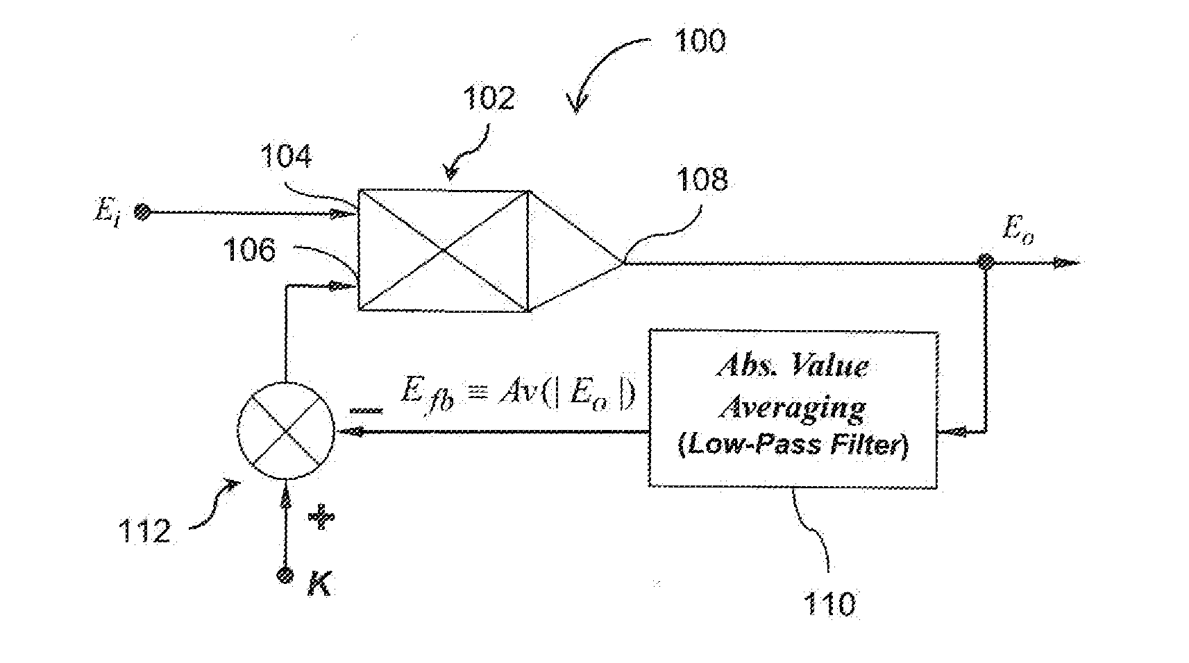
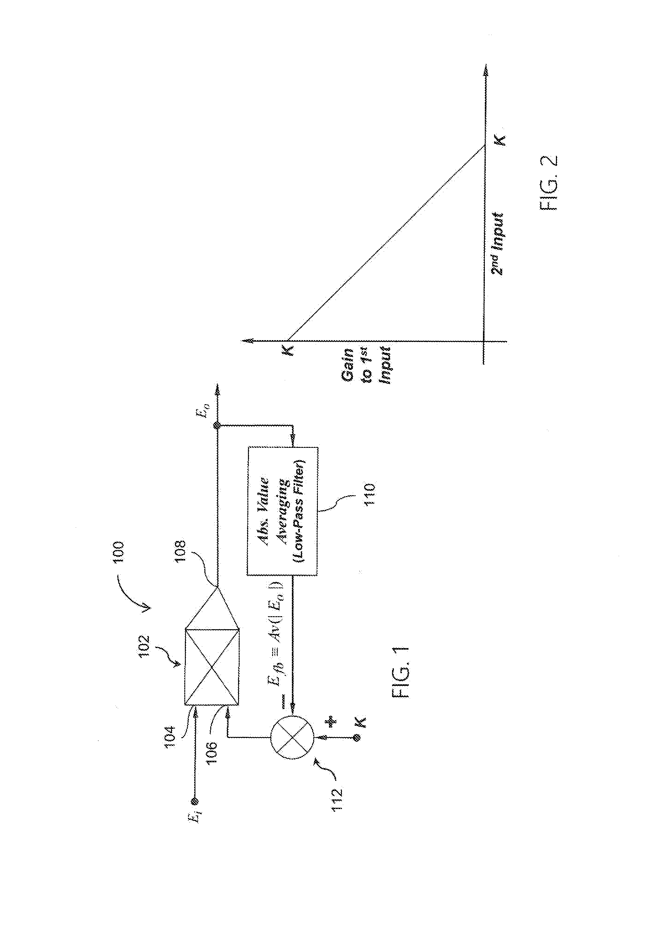
[0038]Referring now to the drawings, FIG. 1 is an embodiment of a DRC device and method according to a neuromorphic fb-AGC model 100. In the neuromorphic fb-AGC model, each sample of an acquired sound signal Ei is input to a first input 104 of a signal multiplier 102. The soun...


PUM


Abstract

A method compresses the dynamic range of an audio signal. The audio signal is multiplied by a scalar to produce a scalar multiplied version of the audio signal. The audio signal is rectified to produce a rectified version of the audio signal. The rectified version of the audio signal is modified according to a well-defined function to produce a modified rectified version of the audio signal. An output signal is produced based on a ratio between the scalar multiplied version of the audio signal and the modified rectified version of the audio signal. The output signal has a dynamic range less than the dynamic range of the audio signal.

Description

TECHNICAL FIELD[0001]The present invention relates to processing of sound and, more particularly, to dynamic range compression of sound.BACKGROUND OF THE INVENTION[0002]The maximum allowable sound level the human ear can accommodate without damage is 90 db. Normal daily background noise loudness can easily reach 70 db. This implies that if we are to secure safe and sound hearing of some audial content to a person, we must see to it that said content shall be provided between 70 dB and 90 dB loudness levels, which is 20 dB, or factor 120, or about 7 bits in digital terms, of dynamic range (DR). It turns out however that loudness levels that a human can be daily exposed to may exceed 200 dB, which equals 1020 times the minimum audible level of 0 dB, or some 33 bits of DR.[0003]The prior art in DRC of sound commonly consists of 1:1 mappings, such as e.g., logarithmic curves or piecewise linear input-output curves, where the new sample value is determined according to the original sampl...

Claims


Application Information

Patent Timeline
IPC IPC(8): H03G7/00H04R25/00H03G9/18H04R3/04
CPCH03G7/007H03G7/004H04R25/356H04R3/04H03G9/18G10L19/005G10L19/012G10L21/003G10L21/04H04R25/35
Inventor SHEFER, MORDECHAI
Owner SHEFER YAFIT
Why Eureka
Try Eureka