
Control system for four-wheel drive vehicle

Active Publication Date: 2016-08-11
TOYOTA JIDOSHA KK
View PDF7 Cites 14 Cited by
  • Summary
  • Abstract
  • Description
  • Claims
  • Application Information

AI Technical Summary

Benefits of technology

The patent text describes a device that controls the distribution of driving force between the right and left wheels in a four-wheel drive vehicle. This device can display the driving force and the operating state of the disconnect mechanism, which enables accurate driver recognition. When an abnormality in the vehicle system is detected, the device can quickly inform the driver of the issue and can blink or display the vehicle model image to indicate the abnormality. The technical effect of this device is improved safety and informed driver awareness.

Problems solved by technology

However, when the vehicle shifts from a two-wheel drive mode to the four-wheel drive mode while the vehicle travels in the two-wheel drive mode in a state where rotation of the rotating element is stopped by the disconnect mechanism (hereinafter, referred to as disconnect mode), there is a possibility that it takes time to shift the drive mode.
However, a display device that is able to clearly inform the driver of the operating state of the disconnect mechanism at any time has not been disclosed at the present time.

Method used


Image

  • Control system for four-wheel drive vehicle
  • Control system for four-wheel drive vehicle
  • Control system for four-wheel drive vehicle

Examples


Embodiment Construction

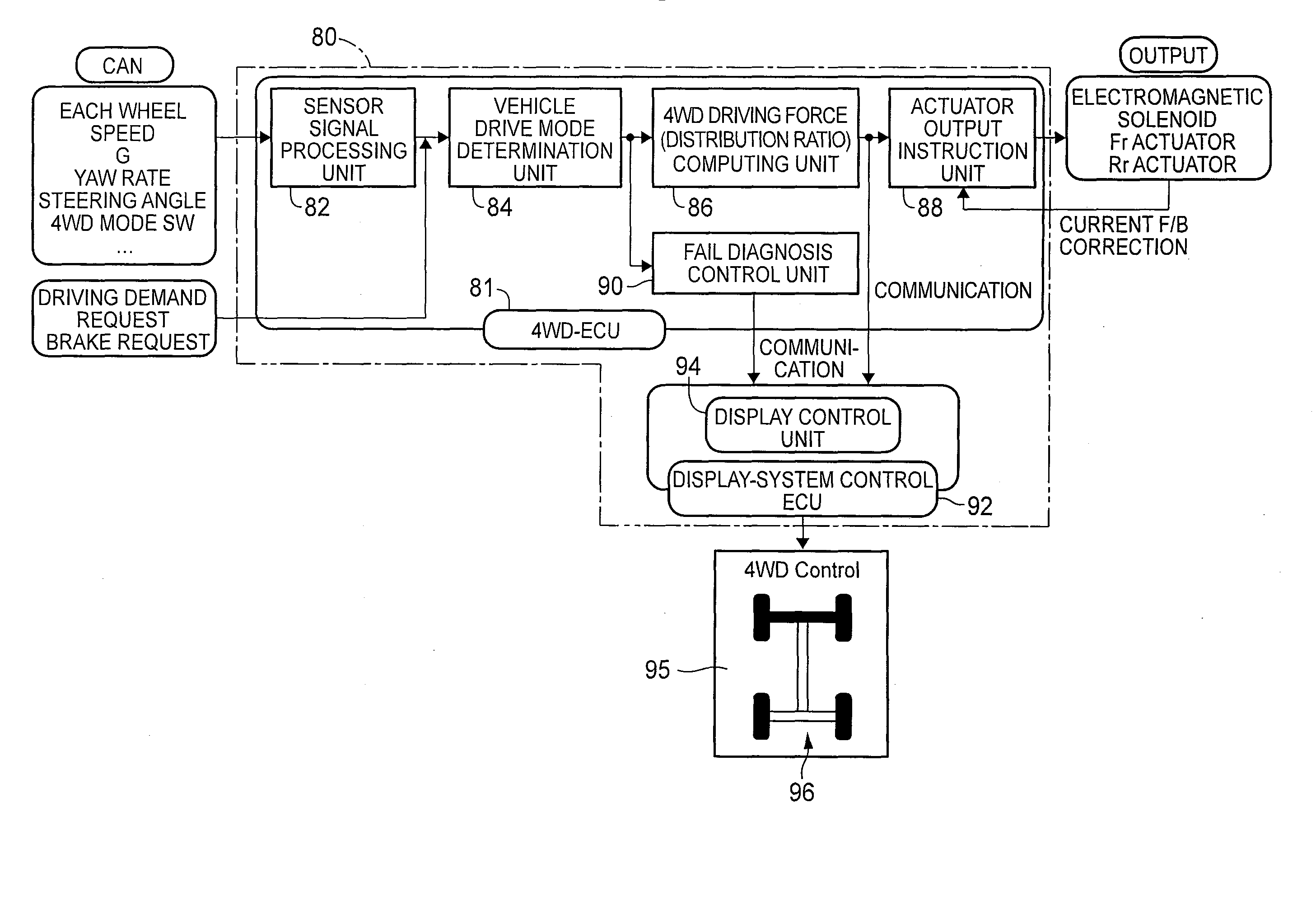
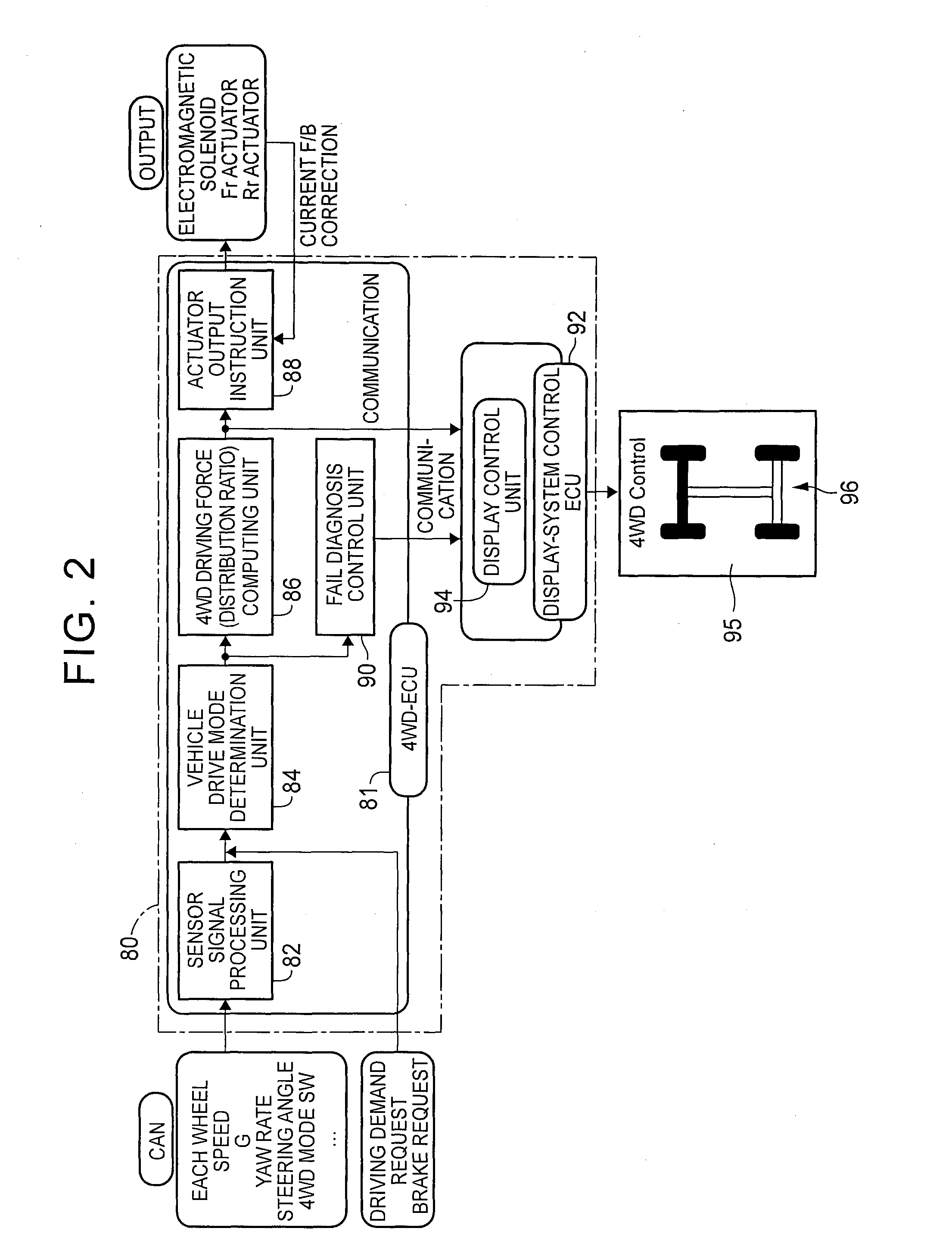
[0043]Hereinafter, embodiments of the invention will be described in detail with reference to the accompanying drawings. In the following embodiments, the drawings are simplified or modified as needed, and the scale ratio, shape, and the like, of each portion are not always accurately drawn.

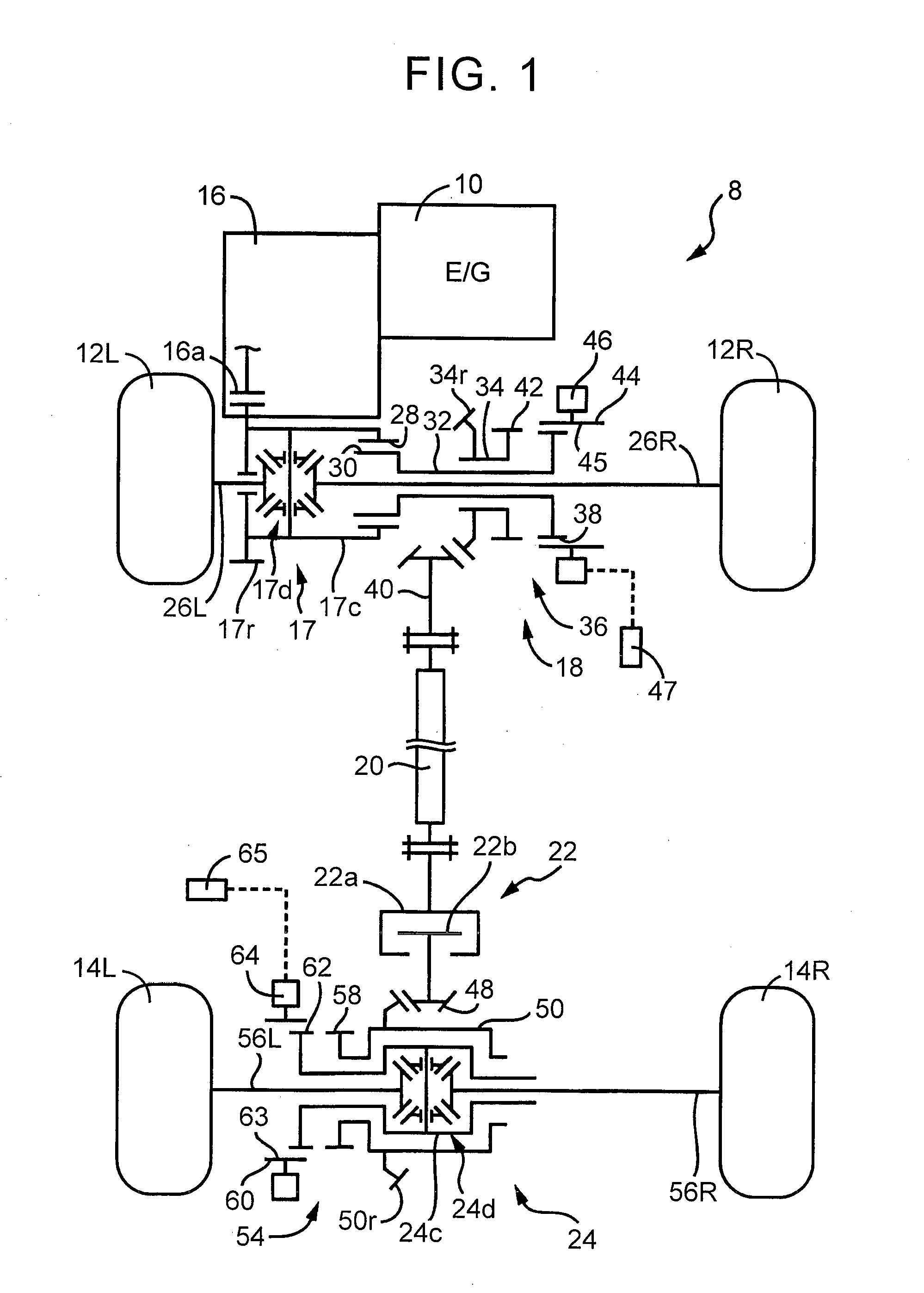
[0044]FIG. 1 is a skeletal view that schematically illustrates the configuration of a four-wheel drive vehicle 8 to which the invention is suitably applied. As shown in FIG. 1, the four-wheel drive vehicle 8 includes a four-wheel drive system based on an FF system. The four-wheel drive vehicle 8 includes an engine 10 as a driving source, and includes a first power transmission path and a second power transmission path. The first power transmission path transmits power of the engine 10 to front wheels 12R, 12L (when not particularly distinguished from each other, referred to as front wheels 12). The second power transmission path transmits power of the engine 10 to rear wheels 14R, 14L (when not p...


PUM


Abstract

A rotation state of each rotating element of a four-wheel drive vehicle and an operating state of each engagement element of a disconnect mechanism, corresponding to an operating state of the disconnect mechanism, are displayed on or near a vehicle model image on a vehicle display. Thus, it is possible to inform a driver of the operating state of the disconnect mechanism at any time. Thus, the driver is able to recognize the operating state of the disconnect mechanism at any time, so the driver is able to carry out driving based on the operating state.

Description

BACKGROUND OF THE INVENTION[0001]1. Field of the Invention[0002]The invention relates to a four-wheel drive vehicle including a disconnect mechanism that is selectively operated to interrupt transmission of power to a predetermined rotating element. More particularly, the invention relates to a device that indicates an operating state of the disconnect mechanism.[0003]2. Description of Related Art[0004]There is known a technique for displaying the distribution of driving force (the distribution of torque), which is transmitted to front and rear drive wheels of a four-wheel drive vehicle, on a vehicle model image of an in-vehicle display provided at an in-vehicle driver seat. This is a torque distribution display device for a four-wheel drive vehicle, described in Japanese Patent Application Publication No. 61-244627 (JP 61-244627 A). In the torque distribution display device described in JP 61-244627 A, the distribution of driving force during traveling is displayed at any time so a...

Claims


Application Information

Patent Timeline
IPC IPC(8): B60W30/18B60K35/00B60W10/10B60W10/02B60W10/06
CPCB60K17/35B60K17/3515B60K35/00B60W2710/06B60W2710/02B60W2710/10B60W10/10B60W10/06B60W10/02B60K2350/352B60W30/18B60K35/81B60W30/182B60K23/08
Inventor SHIMIZU, SATOSHIOBAYASHI, YOSHIROHORIE, RYOTAMIZOGUCHI, NORIHIROMUKOUGAWA, SHINTAROUIWATSUKI, KUNIHIRO
Owner TOYOTA JIDOSHA KK
Learn More