Thermoelectric conversion module

Inactive Publication Date: 2016-08-11
NIPPON THERMOSTAT
View PDF8 Cites 13 Cited by
  • Summary
  • Abstract
  • Description
  • Claims
  • Application Information

AI Technical Summary

Benefits of technology

[0029]According to the present invention, by forming the second electrodes into integrated units corresponding to the parallel groups, the plurality of second

Problems solved by technology

Using the Seebeck effect to generate electricity with thermoelectric conversion elements results in very low induced voltages.
However, connecting thermoelectric conversion elements i

Method used


Image

  • Thermoelectric conversion module
  • Thermoelectric conversion module
  • Thermoelectric conversion module

Examples


Example

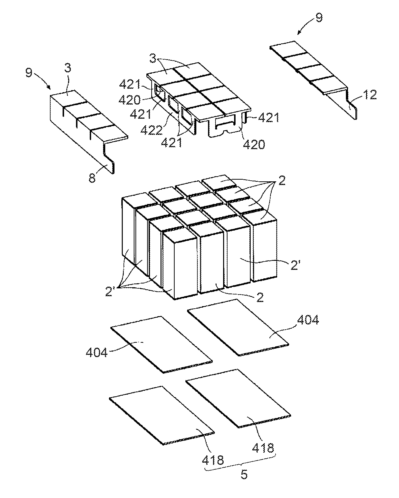
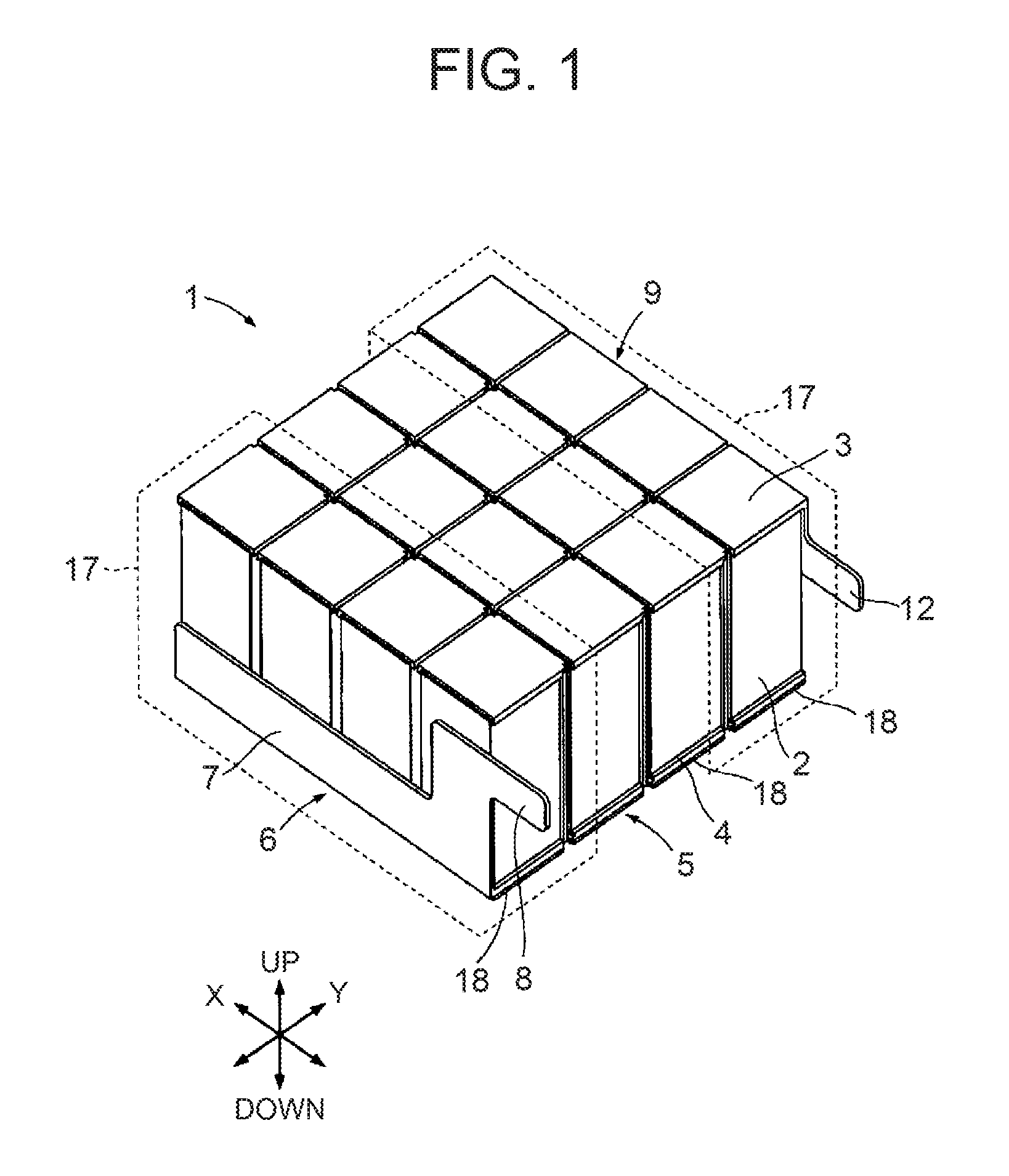
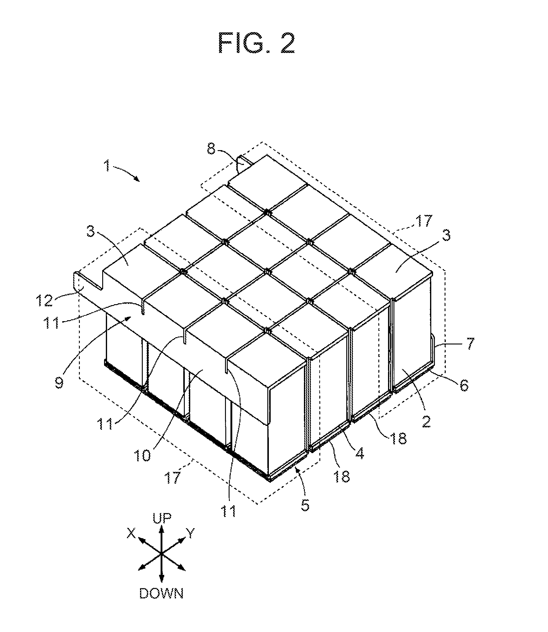
[0047]With reference to FIG. 1 through FIG. 5, a description is given of a first embodiment of a thermoelectric conversion module of the present invention. The thermoelectric conversion module shown in FIG. 1 though FIG. 3 is a so-called uni-leg type, in which a plurality of n-type thermoelectric conversion elements 2 are electrically connected.

[0048]The thermoelectric conversion elements 2 are made of magnesium silicide (Mg2Si), shaped into square columns. Conventionally, many of the materials used for thermoelectric conversion elements are toxic (including materials that may become toxic) as well as expensive. By contrast, Mg2Si is not toxic and is environmentally friendly, and moreover is plentiful and inexpensive. In addition, Mg2Si has a low specific gravity, thus allowing very lightweight thermoelectric conversion elements to be produced. For these reasons, Mg2Si has become the material of choice for thermoelectric conversion elements.

[0049]First electrodes 3 are bonded to the...

Example

[0080]A notched groove 213 of a second embodiment to be described below may be provided to the connecting portions 13 of the first embodiment. Providing a notched groove to the connecting portions 13 facilitates vertical expansion and contraction of the connecting portion 13, so that it can more easily track deformations due to thermal expansion and thermal contraction of the thermoelectric conversion elements 2. In addition, even if there appears unevenness in the heights of the thermoelectric conversion elements 2, by deforming the notched grooves the first electrodes 3 can be pressed against the thermoelectric conversion elements 2 to securely bind the thermoelectric conversion elements 2 with the first electrodes 3 and the second electrodes 4. Thus, the notched grooves are the equivalent of a tracking portion in the present invention. The tracking portions of the present invention are not limited to notched grooves, however, and may be any configuration that can expand and contr...

Example

Third Embodiment

[0100]Next, with reference to FIG. 12 through FIG. 14, a description is given of a third embodiment of the present invention. It should be noted that parts that are identical to those of the first or second embodiments are given the same reference numerals and descriptions thereof are omitted. In addition, reference numeral 17′ in FIG. 12 and FIG. 13 denotes series groups of the third embodiment.

[0101]The thermoelectric conversion module 301 of the third embodiment is a so-called pi-type thermoelectric conversion module consisting of n-type thermoelectric conversion elements 2 and p-type thermoelectric conversion elements 2′, electrically connected. As shown in FIG. 12, the elements are arranged p-type, n-type, p-type, n-type, in that order, from the proximal end in the Y direction. In the X direction, four thermoelectric conversion elements of the same type are arrayed.

[0102]In the so-called pi-type thermoelectric conversion module, the p-type thermoelectric convers...


PUM


Abstract

A thermoelectric conversion module that provides improved reliability while maintaining good induced voltage. The thermoelectric conversion module includes a base 5; a plurality of first electrodes 3; a plurality of thermoelectric conversion elements 2 each electrically connected to one of the first electrodes 3 at one end thereof; and a plurality of second electrodes 4, each electrically connected to another end of the thermoelectric conversion elements 2; a plurality of parallel groups 17 connecting the thermoelectric conversion elements 2 in parallel; and the parallel groups 17 connected in series, or a plurality of series groups connecting the thermoelectric conversion elements 2 in series, with the series groups connecting in parallel.

Description

TECHNICAL FIELD[0001]The present invention relates to a thermoelectric conversion module that uses the Seebeck effect to generate electricity and the Peltier effect to carry out heating and cooling.BACKGROUND ART[0002]Conventionally, a thermoelectric conversion module that arranges a plurality of thermoelectric conversion elements each having an electrode at both ends is known (see, for example, Patent Document 1).[0003]The thermoelectric conversion module of Patent Document 1 is composed of a so-called pi-type thermoelectric conversion module consisting of two types of thermoelectric conversion elements, n-type thermoelectric conversion elements and p-type thermoelectric conversion elements, arranged in alternating sequence and electrically connected in series.[0004]With the thermoelectric conversion module of Patent Document 1, the hot side of the thermoelectric conversion module is made contactless with respect to the heat chamber inside the resistance heating furnace covered in ...

Claims


Application Information

Patent Timeline
IPC IPC(8): H01L35/10
CPCH01L35/32H01L35/10H01L35/04H10N10/82H10N10/81H10N10/17
Inventor SUDA, HIROSHINEMOTO, TAKASHISATO, JUNICHI
Owner NIPPON THERMOSTAT
Why Eureka
Try Eureka