
Variable elastic modulus cushion disposed within a distal cup of a prosthetic socket

a technology of elastic modulus and cushion, which is applied in the field of prosthetic socket systems, can solve the problems of inherently difficult suspension and general non-residual limbs, and achieve the effect of improving mechanical properties and improving stability

Inactive Publication Date: 2016-08-18
LIM INNOVATIONS
View PDF4 Cites 19 Cited by
  • Summary
  • Abstract
  • Description
  • Claims
  • Application Information

AI Technical Summary

Benefits of technology

The invention is about a cushion for a prosthetic socket that is designed to fit a patient's residual limb. The cushion has a specific structure and is made using a 3D printing process. The cushion has a customizable structure that can be tailored to the patient's physical characteristics and the needs of the prosthetic socket. The cushion has a unique combination of solid and liquid thermoplastic elastomer, which makes it comfortable and adaptable to the patient's needs. The cushion can be made using a single monolithic structure or multiple structures with different fill volumes. The cushion can also have a void volume and a relative fill volume gradient to provide better support and comfort for the patient. The invention provides a more comfortable and customizable prosthetic socket for amputee patients.

Problems solved by technology

It is not enough that a prosthetic socket simply fit, however well, on the residual limb of a patient; it must also resist distal slippage, up and down pistoning when the user is walking, and rotation.
Suspension is inherently difficult, however, and the residual limb needs to be treated gently, since damaging the skin on the residual limb is completely intolerable.
Also, the residual limb generally does not provide points of mechanical advantage that could contribute to suspension.

Method used


Image

  • Variable elastic modulus cushion disposed within a distal cup of a prosthetic socket
  • Variable elastic modulus cushion disposed within a distal cup of a prosthetic socket
  • Variable elastic modulus cushion disposed within a distal cup of a prosthetic socket

Examples


Embodiment Construction

[0050]Aspects of the technology disclosed herein are directed toward improvements in and around the distal base portion of a prosthetic socket. In one aspect, the technology relates to mechanics of suspending a prosthetic socket on a residual limb. These improvements include a strap-lanyard suspension arrangement.

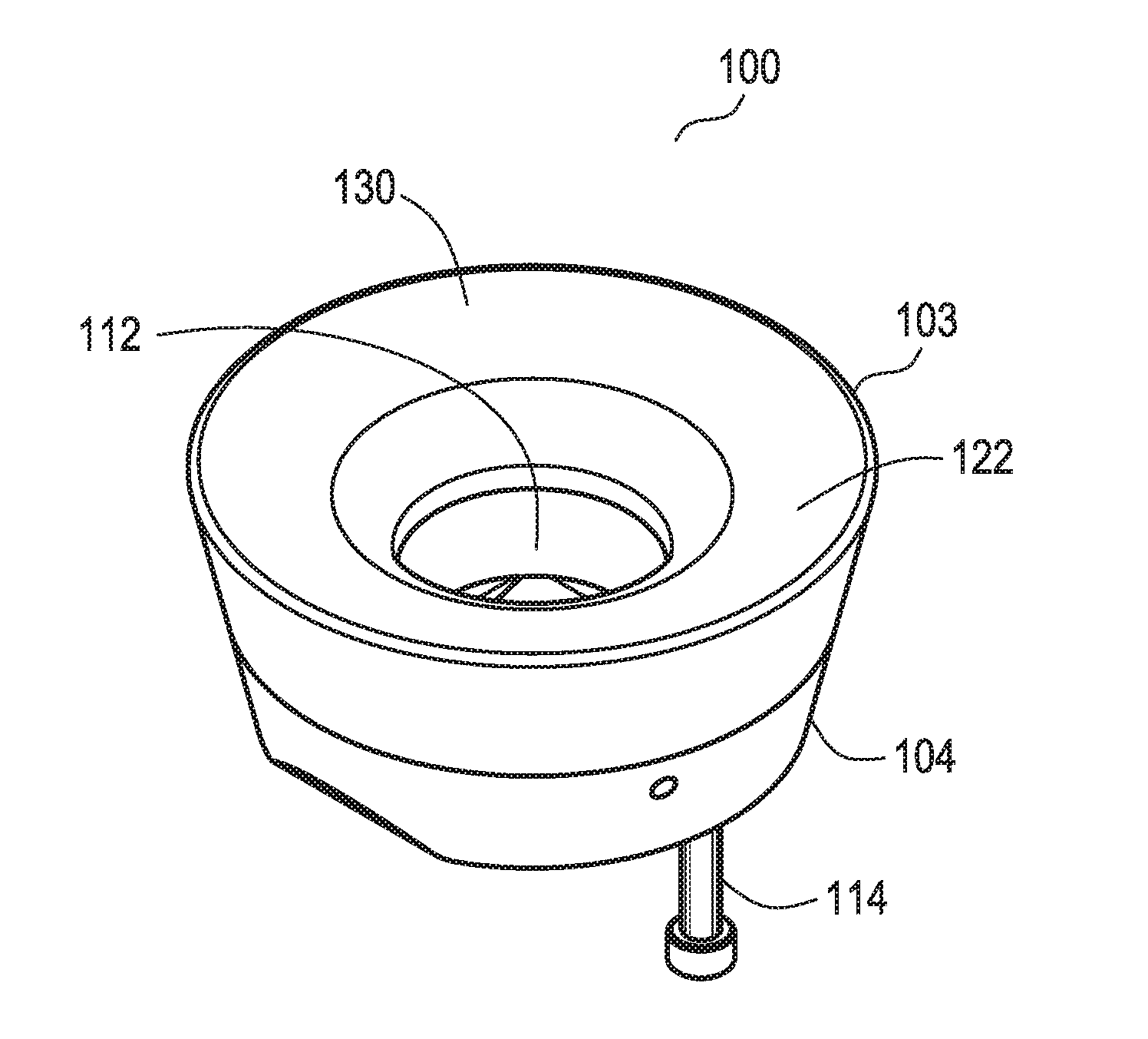
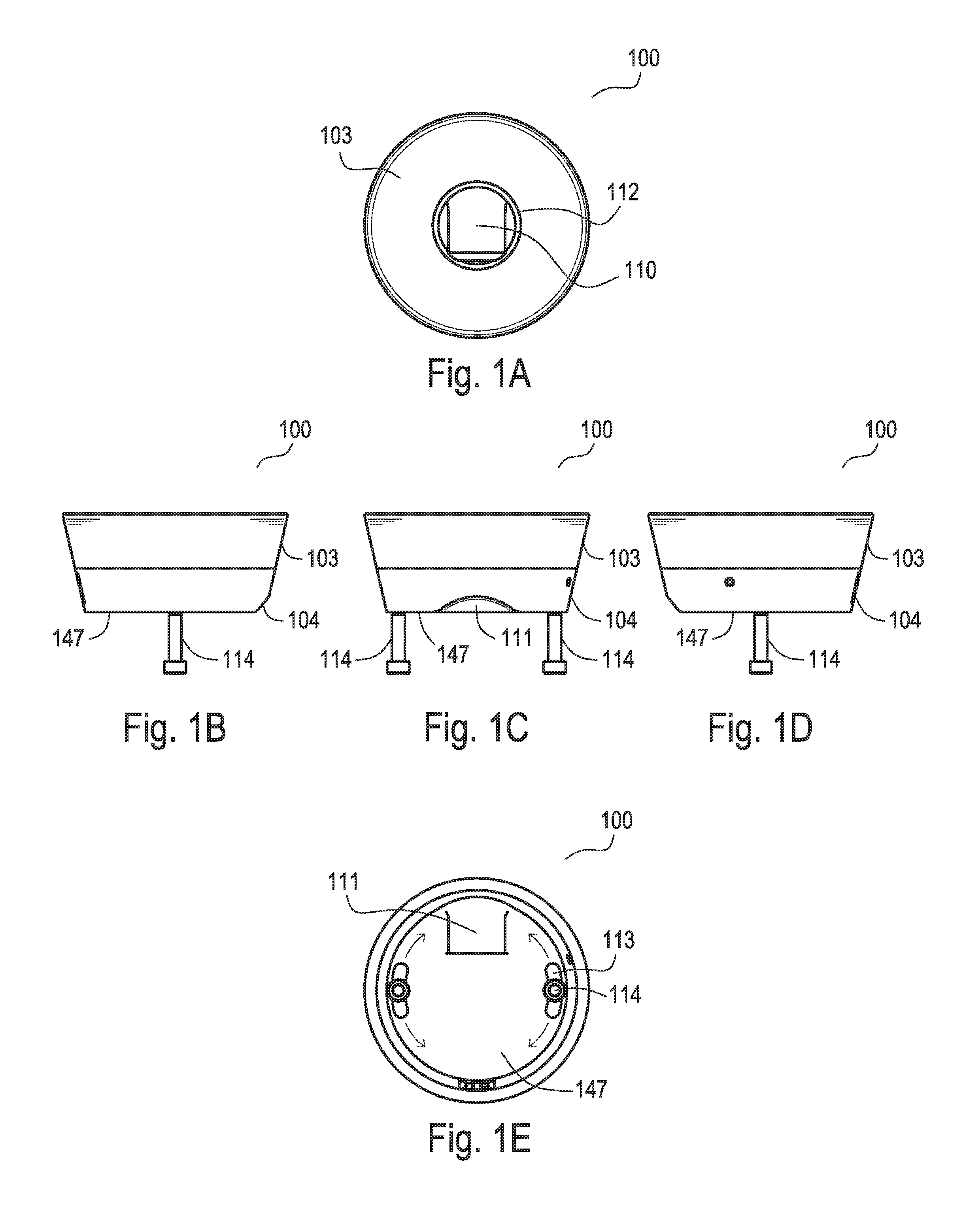
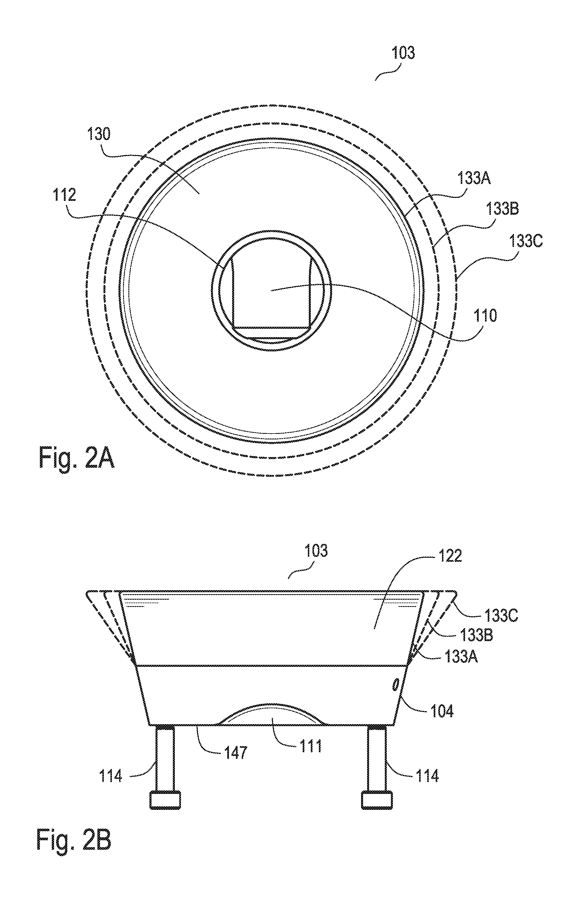
[0051]In another aspect, the technology relates to a cushion that engages and supports the distal portion of the residual limb. A variable elastic modulus cushion is positioned within proximal disk or shock absorbing pad of prosthetic socket distal cup. Embodiments of the cushion may be 3D printed, and they may include variable and customizable patterns of elasticity and durometer that can be directed to optimizing fit and therapeutic benefit. These patterns are a result of at least two variables: (a) the variation in thermoplastic elastomer fill density (solid volume / total volume) within regional subsets of the total volume, and (b) the structures formed by the interplay o...


PUM


Abstract

A cushion for a distal cup of a prosthetic socket has a total volume that includes a solid thermoplastic composition volume and a void volume. A ratio of the solid composition relative volume to the total volume yields a relative thermoplastic elastomer fill volume that is correlated with an elastic modulus of the cushion. The relative thermoplastic elastomer fill volume can vary regionally within the cushion in a customized manner, and accordingly, so can the elastic modulus and the durometer. Varying the elastic modulus or durometer regionally within a cushion, such as by 3D printing the cushion, provides therapeutic and prophylactic benefits in the application of the cushion to articles that interface with the body, such as a cushion disposed in the distal portion of a prosthetic socket for a residual limb of an amputee.

Description

CROSS-REFERENCE TO RELATED APPLICATIONS[0001]This patent application claims the priority and benefit of U.S. Provisional Application Nos. 62 / 117,501, filed Feb. 18, 2015, entitled “Strap-Based Mechanism for Suspending a Prosthetic Device on a Residual Limb,” and 62 / 128,218, filed Mar. 4, 2015, entitled “Modular Prosthetic Socket,” and 62 / 163,717, filed May 19, 2015, entitled “Prosthetic Socket Distal Cup with a Strap Lanyard Suspension Mechanism and a Variable Elastic Modulus Cushion.” All of the above-referenced applications are herein incorporated in their entireties by reference.[0002]This patent application is further related to the following U.S. Patent Applications: application Ser. No. 13 / 675,761, entitled “Modular prosthetic sockets and methods for making same,” filed Nov. 13, 2012; application Ser. No. 14 / 213,788, entitled “Modular prosthetic sockets and methods for making and using same,” filed Mar. 14, 2014; and application Ser. No. 62 / 007,742, entitled “Apparatus and met...

Claims


Application Information

Patent Timeline
IPC IPC(8): A61F2/78A61F2/80
CPCA61F2/7812A61F2/80B33Y50/02B33Y10/00B33Y80/00A61F2002/785A61F2/5046A61F5/30A61F2002/505A61F2002/5056A61F2002/7862A63B2071/1258A63B71/10
Inventor CESPEDES, JUAN JACOBOWILLIAMS, JESSE ROBERTHURLEY, GARRETT RAY
Owner LIM INNOVATIONS
Learn More