Projection optical system and projection type display device

Active Publication Date: 2016-08-25
FUJIFILM CORP
View PDF9 Cites 17 Cited by
  • Summary
  • Abstract
  • Description
  • Claims
  • Application Information

AI Technical Summary

Benefits of technology

[0035]In addition, the projection type display device of the present disclosure is equipped with the projection optical system of the present

Problems solved by technology

Although the use of the aspherical mirror is suited for widening the angle of view, the size of the mirror will be large, which is extremely disadv

Method used


Image

  • Projection optical system and projection type display device
  • Projection optical system and projection type display device
  • Projection optical system and projection type display device

Examples


Embodiment Construction

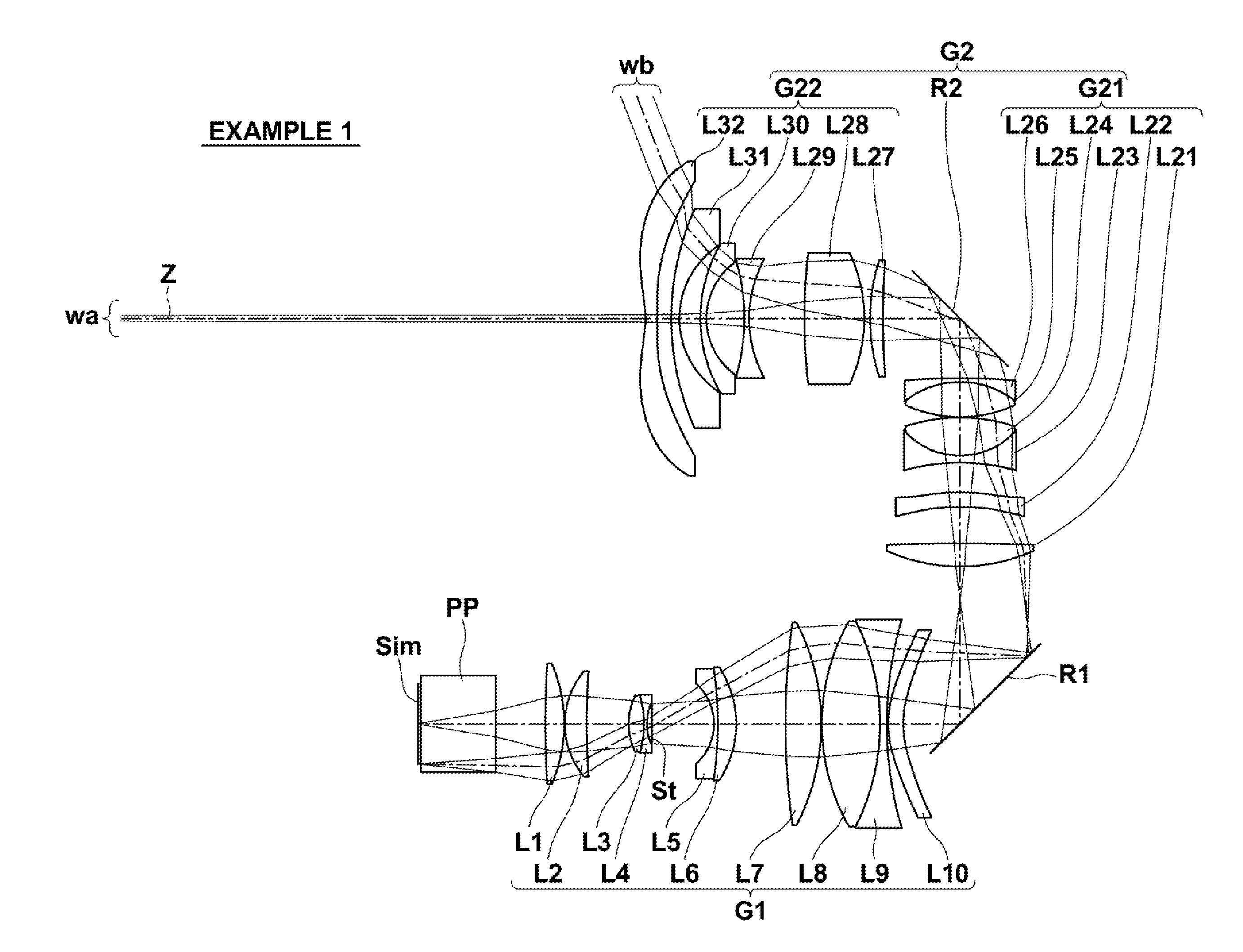
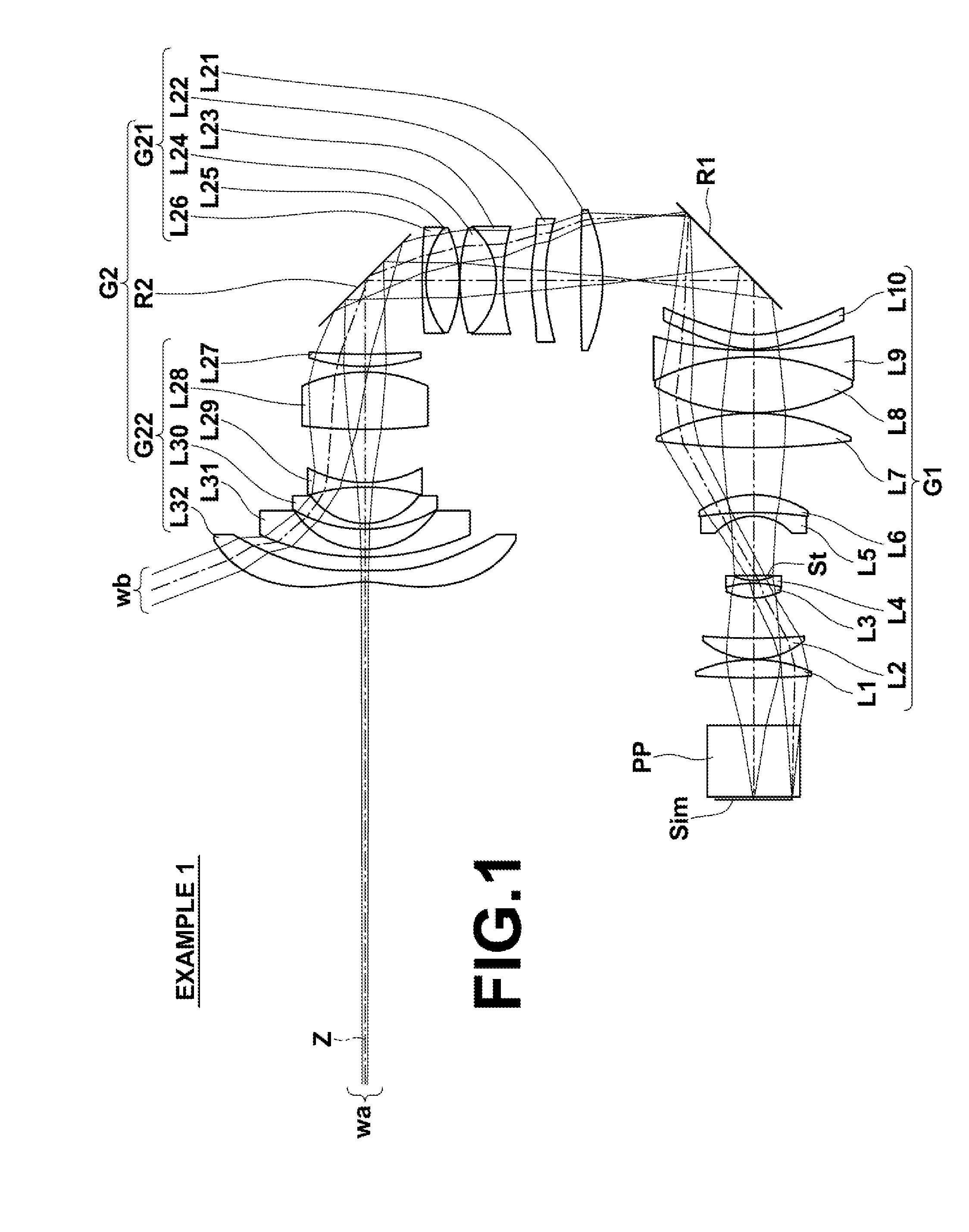
[0051]Hereinafter, embodiments of the present disclosure will be described in detail with reference to the accompanying drawings. FIG. 1 is a sectional diagram that illustrates the configuration of a projection optical system according to an embodiment of the present disclosure. The example illustrated in FIG. 1 corresponds to a projection optical system of Example 1 to be described later. In FIG. 1, the side of an image display surface Sim is the reduction side, and the side of a final lens L32 of the second optical system G2 is the magnification side. The aperture stop St illustrated in FIG. 1 does not necessarily represent the size or shape thereof, but the position thereof along an optical axis Z. In addition, FIG. 1 also shows an axial light beam wa and a light beam wb at a maximum angle of view.

[0052]This projection optical system may be mounted in a projection type display device and utilized to project image information displayed on light valves onto a screen. In FIG. 1, a c...


PUM


Abstract

A projection optical system is constituted by, in order from the reduction side, a first optical system constituted by a plurality of lenses for forming an image displayed by image display elements as an intermediate image, and a second optical system constituted by a plurality of lenses for forming the intermediate image on a magnification side conjugate plane. Conditional Formula (1) below is satisfied.
8.20<Imφ·f2/f2<20.00  (1)

Description

CROSS REFERENCE TO RELATED APPLICATIONS[0001]The present application claims priority under 35 U.S.C. §119 to Japanese Patent Application No. 2015-035082 filed on Feb. 25, 2015. The above application is hereby expressly incorporated by reference, in its entirety, into the present application.BACKGROUND[0002]The present disclosure is related to a projection optical system and a projection type display device. Particularly, the present disclosure is related to a projection optical system which is favorably suited for use in a projection type display device having light valves such as liquid crystal display elements or DMD's (Digital Micromirror Devices®), and a projection type display device that employs this projection optical system.[0003]Recently, projection type display devices (also referred to as “projectors”) which are equipped with light valves such as liquid crystal display elements and DMD's (Digital Micromirror Devices®) are in wide use, and the performance thereof is increa...

Claims


Application Information

Patent Timeline
IPC IPC(8): G02B13/16G02B13/04H04N9/31G02B13/00
CPCG02B13/16G02B13/0095H04N9/3197H04N9/317G02B13/04G03B21/28G02B13/06G02B13/22
Inventor AMANO, MASARU
Owner FUJIFILM CORP
Why Eureka
Try Eureka