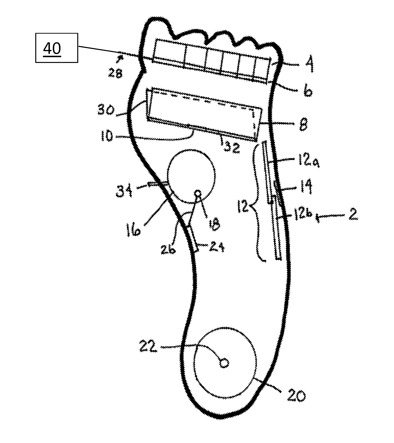
Actuated foot orthotic with sensors

a foot orthotic and sensor technology, applied in the field of foot orthotics, can solve the problems of ulceration of the foot, excessive pressure along the infected footpad area, uncontrollable inflammation, etc., and achieve the effect of determining the deformation of the foo

Inactive Publication Date: 2016-09-01
BOARD OF RGT NEVADA SYST OF HIGHER EDUCATION ON BEHALF OF THE UNIV OF NEVADA RENO
View PDF7 Cites 21 Cited by
  • Summary
  • Abstract
  • Description
  • Claims
  • Application Information

AI Technical Summary

Benefits of technology

[0018]A system is provided for modeling tissue deformation of a foot of a patient as the patient walks relative to an axis of movement. The system can include means for measuring pressure applied by the foot of the patient as the patient walks relative to the axis of movement. In one optional aspect, the means for measuring pressure can include at least one pressure sensor. In another optional aspect, the means for measuring pressure can further include a pressure-sensitive device positioned such that the axis of movement passes through the pressure-sensitive device. The pressure-sensitive device can have a transverse axis substantially perpendicular to the axis of movement and a contact surface, and the at least one pressure sensor can be configured to produce at least one pressure output indicative of a pressure applied to the contact surface as the patient walks over the pressure-sensitive device relative to the axis of movement. Optionally, the pressure-sensitive device can be a pressure-sensitive mat or a pressure-sensitive insole. The system can also include at least one camera. Optionally, the at least one camera can include a plurality of cameras, such as, for example, first and second cameras. Each of the first and second cameras can be configured to produce one or more images of the foot of the patient as the patient walks relative to the axis of movement. The first camera can have an orientation axis positioned substantially perpendicular to the axis of movement. The second camera can have an orientation axis positioned substantially parallel to the axis of movement. The system can further include a processor in operative communication with the at least one pressure sensor and the first and second cameras. The processor can be configured to receive the at least one pressure output from the at least one pressure sensor. The processor can be configured to receive the one or more images produced by the first and second cameras. The processor can be configured to determine deformation of the foot of the patient based upon the one or more images produced by the first and second cameras. The processor can be further configured to correlate the at least one pressure output with a corresponding deformation of the tissue of the foot of the patient to thereby produce a tissue deformation profile. Optionally, the system can include a three-dimensional scanner configured to produce a three-dimensional image of the foot of the patient. The processor can be positioned in operative communication with the three-dimensional scanner and configured to receive the three-dimensional image of the foot of the patient.

Problems solved by technology

However, it has been observed that diabetic patients apply pressure to various footpad regions unevenly, which can lead to foot ulcerations.
These ulcerations are difficult to detect since diabetic patients often experience sensory neuropathy (lack of sensation), leading to excessive pressure along the infected footpad areas.
These elevated pressure levels can lead to uncontrollable inflammation, focal tissue ischemia, necrosis, and skin ulceration; ultimately, this can result in multiple complications, including greater rates of infection and eventual amputation of infected tissues.
In addition to the reduction in quality of life for affected patients, foot ulceration escalates the medical cost of treating these patients over extended periods.
The depositing results in at least one void occurring within the structure.

Method used


Image

  • Actuated foot orthotic with sensors
  • Actuated foot orthotic with sensors
  • Actuated foot orthotic with sensors

Examples


Embodiment Construction

[0031]The present invention can be understood more readily by reference to the following detailed description, examples, drawings, and claims, and their previous and following description. However, before the present devices, systems, and / or methods are disclosed and described, it is to be understood that this invention is not limited to the specific devices, systems, and / or methods disclosed unless otherwise specified, as such can, of course, vary. It is also to be understood that the terminology used herein is for the purpose of describing particular aspects only and is not intended to be limiting.

[0032]The following description of the invention is provided as an enabling teaching of the invention in its best, currently known embodiment. To this end, those skilled in the relevant art will recognize and appreciate that many changes can be made to the various aspects of the invention described herein, while still obtaining the beneficial results of the present invention. It will als...


PUM


Abstract

Systems and methods of developing a tissue deformation profile for a foot of a patient. The tissue deformation profile can be used to identify a desired configuration for an orthotic device. A method uses a sensing orthotic device to assist in the treatment of foot issues. The orthotic device can have at least two sensors and at least one actuator for adjusting physical parameters of the orthotic device.

Description

CROSS-REFERENCE TO RELATED APPLICATIONS[0001]This application claims priority to U.S. Provisional Patent Application No. 61 / 899,960, filed Nov. 5, 2013, and to U.S. Provisional Patent Application No. 62 / 017,544, filed Jun. 26, 2014, each of which is hereby incorporated herein by reference in its entirety.BACKGROUND[0002]1. Field[0003]The present invention relates to the field of foot orthotics. More particularly, the present invention relates to a tissue deformation model that can be used to develop a foot orthotic. The present invention also relates to the use of sensors in a foot orthotic and the presence of actuators associated with the orthotic that can cause alteration in the shape, performance and position of the orthotic by internal (embedded) or external (remote, wired or wireless) processor control.[0004]2. Background of the Art[0005]The human foot functions in a unique way to provide the body with balance between support and mobility in order to optimize human locomotion. ...

Claims


Application Information

Patent Timeline
Patent Type & Authority Applications(United States)
IPC IPC(8): A61B5/103A43B3/00A61B5/00A43B17/00
CPCA61B5/1038A43B17/00A43B3/0005A61B5/7246A61B2562/0247A61B5/6807A61B5/4836A61B5/7275A61B5/0077A43D1/025A61B5/6892A61B5/112A61B5/1127A61B5/1128A61B5/447A61B5/442A61B5/445A61B5/0036A43B3/38A61F5/34A61F5/14A43B3/34
Inventor TRABIA, MOHAMEDDUFEK, JANET
Owner BOARD OF RGT NEVADA SYST OF HIGHER EDUCATION ON BEHALF OF THE UNIV OF NEVADA RENO
Why Eureka
Try Eureka