Optical System and Image Pickup Apparatus

a technology which is applied in the field of optical system and image pickup apparatus, can solve the problem of insufficient performance of optical system, and achieve the effect of small imaging system

Active Publication Date: 2016-09-01
TAMRON
View PDF0 Cites 9 Cited by
  • Summary
  • Abstract
  • Description
  • Claims
  • Application Information

AI Technical Summary

Benefits of technology

[0012]According to the present invention, it becomes possible to provide small, high-performance, and large-aperture optical system and image pickup apparatus which are suitable for a small imaging system.

Problems solved by technology

However, in the optical system described in Japanese Patent Application Laid-Open No. 7-199066, chromatic aberration correction is insufficient, and so the performance of the optical system is not high enough.

Method used


Image

  • Optical System and Image Pickup Apparatus
  • Optical System and Image Pickup Apparatus
  • Optical System and Image Pickup Apparatus

Examples


example 1

(1) Construction of Optical System

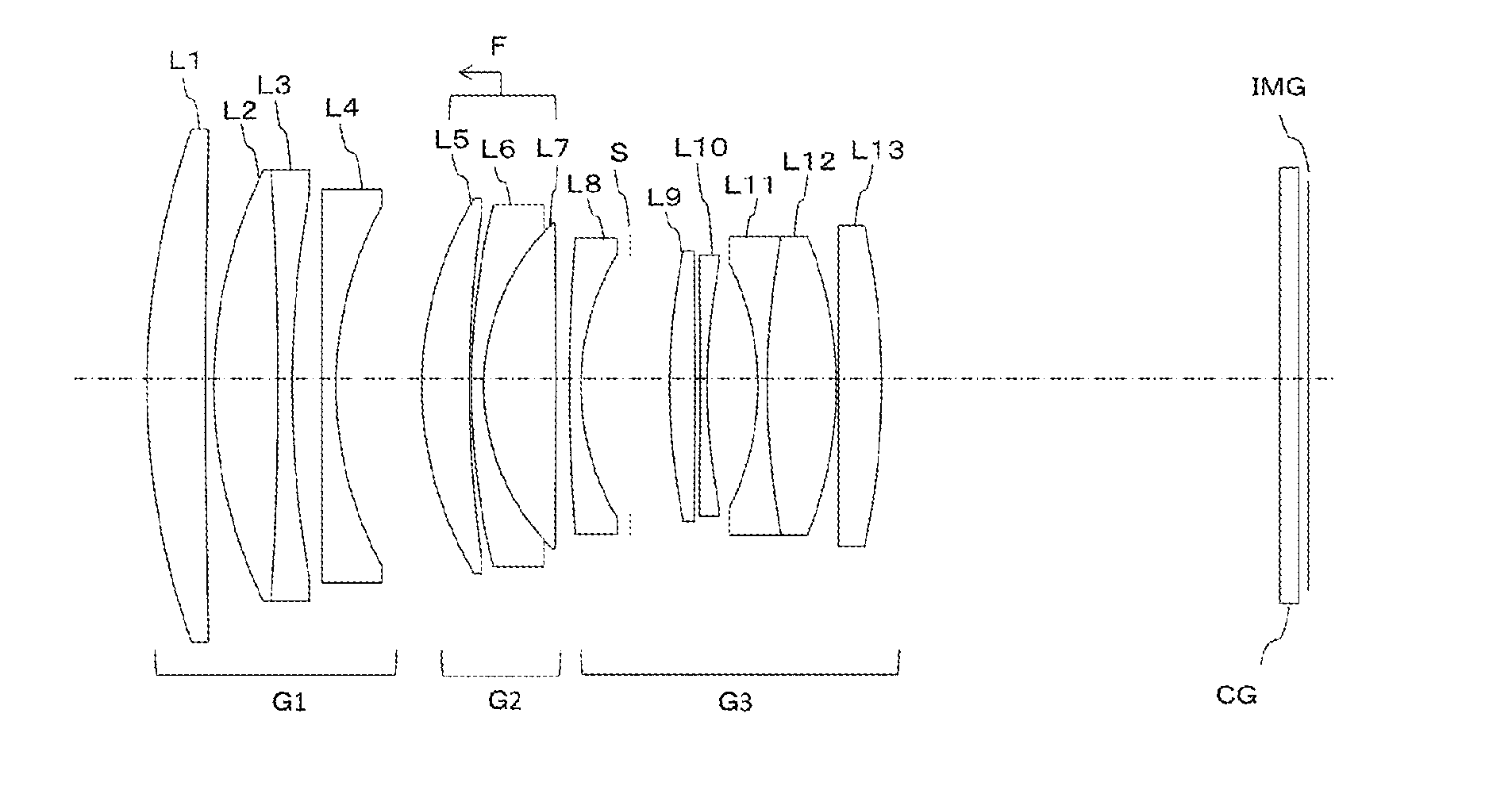
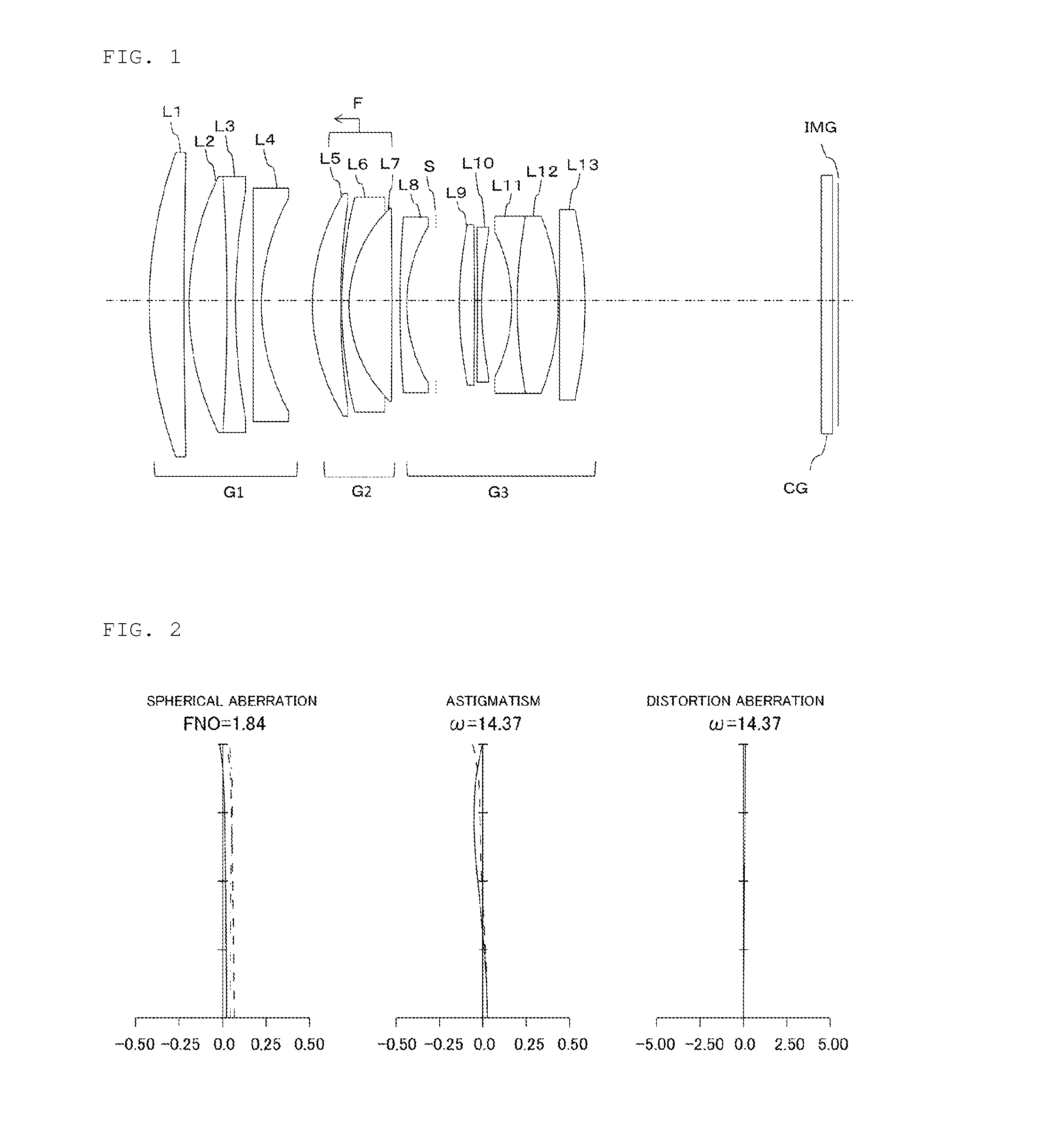
[0085]FIG. 1 is a cross sectional view of lenses for illustrating the lens construction when an optical system of Example 1 according to the present invention focuses at infinity. The optical system includes, in order from the object side: a first lens group G1 having positive refractive power; a second lens group G2 having positive refractive power; and a third lens group G3 having positive refractive power.

[0086]The first lens group G1 includes, in order from the object side: a lens L1 having positive refractive power; a cemented lens formed by cementing a lens L2 having positive refractive power and a lens L3 having negative refractive power; and a lens L4 having negative refractive power with a concave facing the image side.

[0087]The second lens group G2 includes, in order from the object side: a lens L5 having positive refractive power with a convex facing the object side; and a cemented lens formed by cementing a lens L6 having negative refrac...

example 2

(1) Construction of Optical System

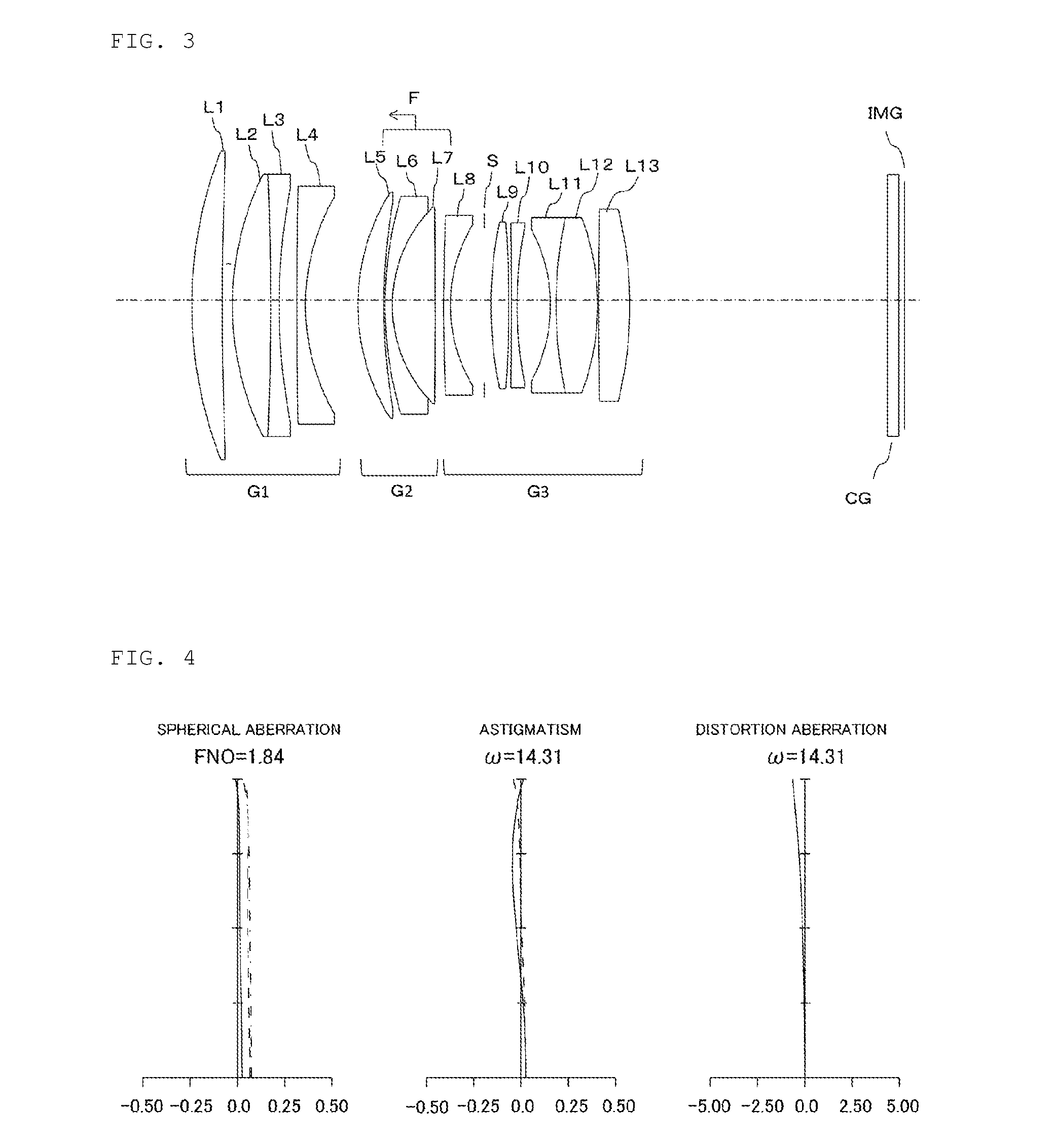
[0094]FIG. 3 is a cross sectional view of lenses for illustrating the lens construction when an optical system of Example 2 according to the present invention focuses at infinity. The optical system includes, in order from the object side: a first lens group G1 having positive refractive power; a second lens group G2 having positive refractive power, and a third lens group G3 having positive refractive power.

[0095]The first lens group G1 includes, in order from the object side: a lens L1 having positive refractive power; a cemented lens formed by cementing a lens L2 having positive refractive power and a lens L3 having negative refractive power; and a lens L4 having negative refractive power with a concave facing the image side.

[0096]The second lens group G2 includes, in order from the object side: a lens L5 having positive refractive power with a convex facing the object side; and a cemented lens formed by cementing a lens L6 having negative refrac...

example 3

(1) Construction of Optical System

[0101]FIG. 5 is a cross sectional view of lenses for illustrating the lens construction when an optical system of Example 3 according to the present invention focuses at infinity. The optical system includes, in order from the object side: a first lens group G1 having positive refractive power; a second lens group G2 having positive refractive power; and a third lens group G3 having positive refractive power.

[0102]The first lens group G1 includes, in order from the object side: a lens L1 having positive refractive power; a cemented lens formed by cementing a lens L2 having positive refractive power and a lens L3 having negative refractive power; and a lens L4 having negative refractive power with a concave facing the image side.

[0103]The second lens group G2 includes, in order from the object side: a lens L5 having positive refractive power with a convex facing the object side; and a cemented lens formed by cementing a lens L6 having negative refrac...


PUM


Abstract

An optical system of the present invention includes, in order from an object side: a first lens group G1; a second lens group G2 having positive refractive power; and a third lens group G3 having positive refractive power, wherein the first lens group G1 and the third lens group G3 are fixed in an optical axis direction while the second lens group G2 is moved in an optical axis direction to focus on from an object at infinity to an object at a finite distance, and specified conditions is satisfied.

Description

CROSS-REFERENCE TO RELATED APPLICATION[0001]This application claims priority to Japanese Patent Application No. 2015-038267 filed Feb. 27, 2015, the disclosure of which is hereby incorporated in its entirety by reference.BACKGROUND OF THE INVENTION[0002]1. Field of the Invention[0003]The present invention relates to optical systems and image pickup apparatuses. The present invention more particularly relates to an optical system suitable for an image pickup apparatus with use of a solid-state image sensor, such as digital still cameras and digital video cameras, and to an image pickup apparatus including the optical system.[0004]2. Description of the Related Art[0005]Image pickup apparatuses with use of a solid-state image sensor, such as digital still cameras and digital video cameras, have spread. With recent development of higher-performance, smaller-size, and the like of imaging optical systems, small imaging systems are rapidly spreading in particular.[0006]Such small imaging s...

Claims


Application Information

Patent Timeline
Patent Type & Authority Applications(United States)
IPC IPC(8): G02B9/64G02B13/00G02B27/00
CPCG02B9/64G02B13/0015G02B27/0025G02B15/163G02B13/005G02B13/006G02B27/646
Inventor YAMANAKA, HISAYUKIOKADA, KEISUKESAKAI, TAKAHIKOIWASAWA, YOSHITO
Owner TAMRON
Why Eureka
Try Eureka