Supercharge Your Innovation With Domain-Expert AI Agents!

Terrestrially observable displays from space

a technology of display and telescope, applied in the field of satellites and control arrangements, can solve the problems of large satellites and expensive (heavy) deployment mechanisms and resources

Active Publication Date: 2016-09-08
TECHNION RES & DEV FOUND LTD
View PDF3 Cites 16 Cited by
  • Summary
  • Abstract
  • Description
  • Claims
  • Application Information

AI Technical Summary

Benefits of technology

The patent describes a type of tiny satellite that carries a light to provide visibility from the ground. The light can be turned on for at least a minute using a special battery and can be controlled to shine in a coordinated pattern with other satellites. This invention allows for a new way to create temporary lighting in a single night.

Problems solved by technology

Known solutions require large satellites and expensive (heavy) deployment mechanisms and resources.

Method used


Image

  • Terrestrially observable displays from space
  • Terrestrially observable displays from space
  • Terrestrially observable displays from space

Examples


Embodiment Construction

[0045]The present invention, in some embodiments thereof, relates to displays in space that are observable from the ground, and, more particularly, but not exclusively, to a satellite and control arrangement to provide such a display.

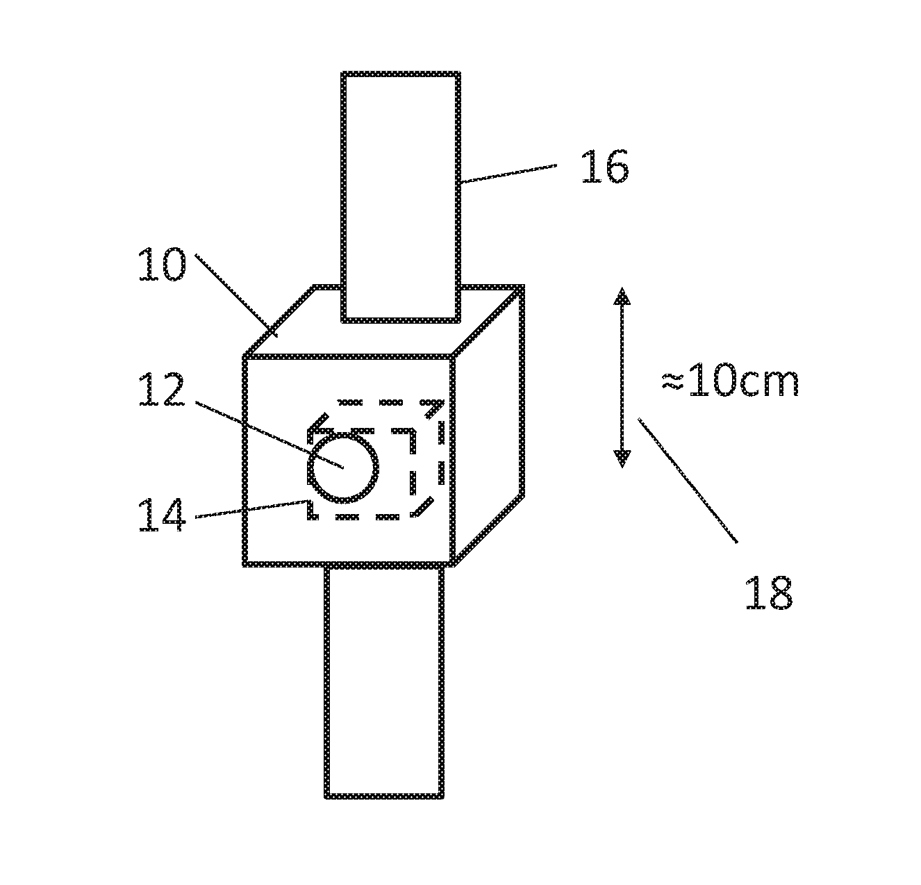
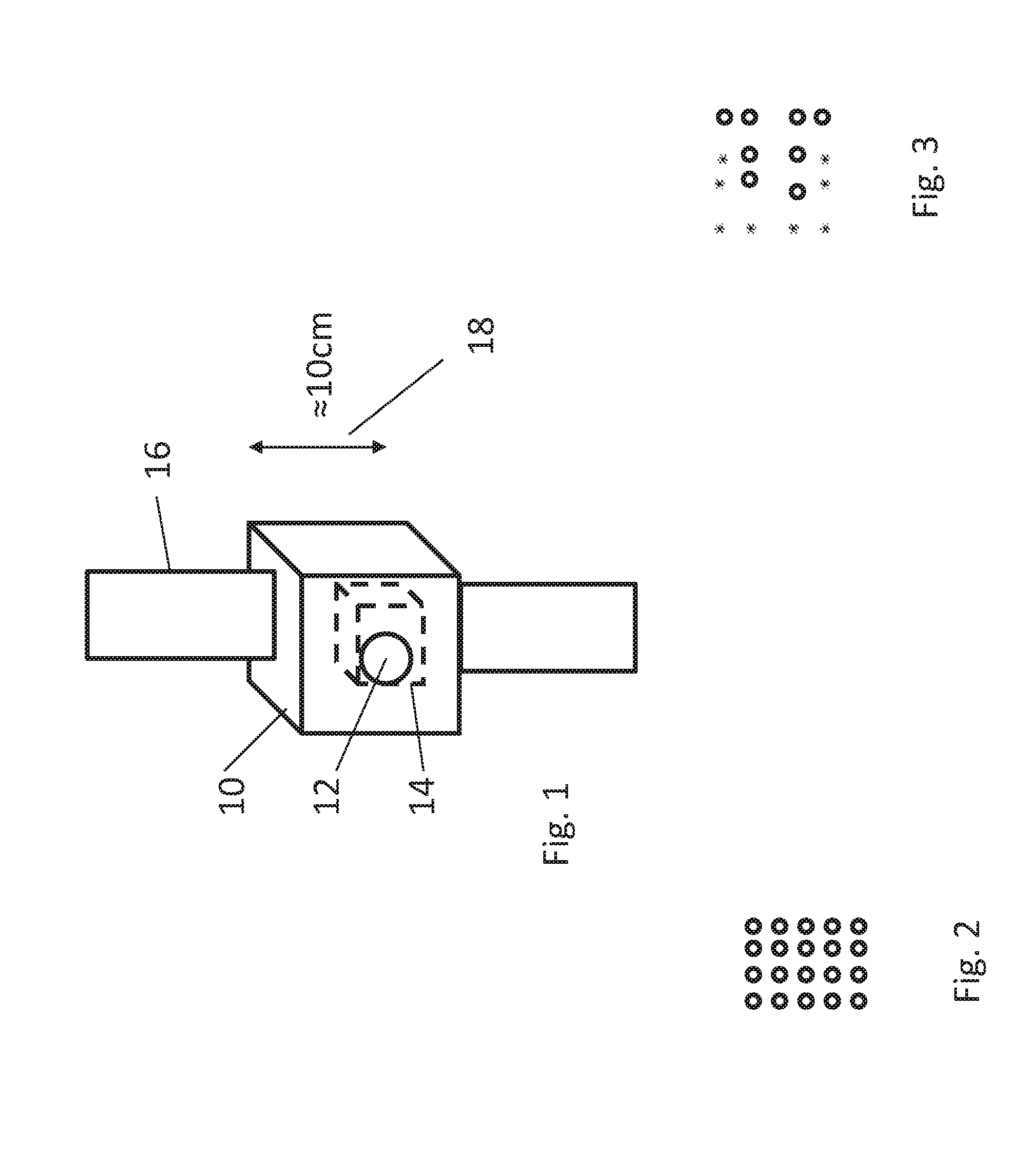
[0046]The present inventions relate to the use of nanosatellites operating in an array to form a sign in space that may be observed on the ground. While the light from any individual satellite may not be meaningful, the array as a whole forms signs that are within the resolving power of the ground based human eye.

[0047]The present embodiments address issues relating to the way in which signs may be formed in light of constraints on available energy, and these include ways to exploit sunlight.

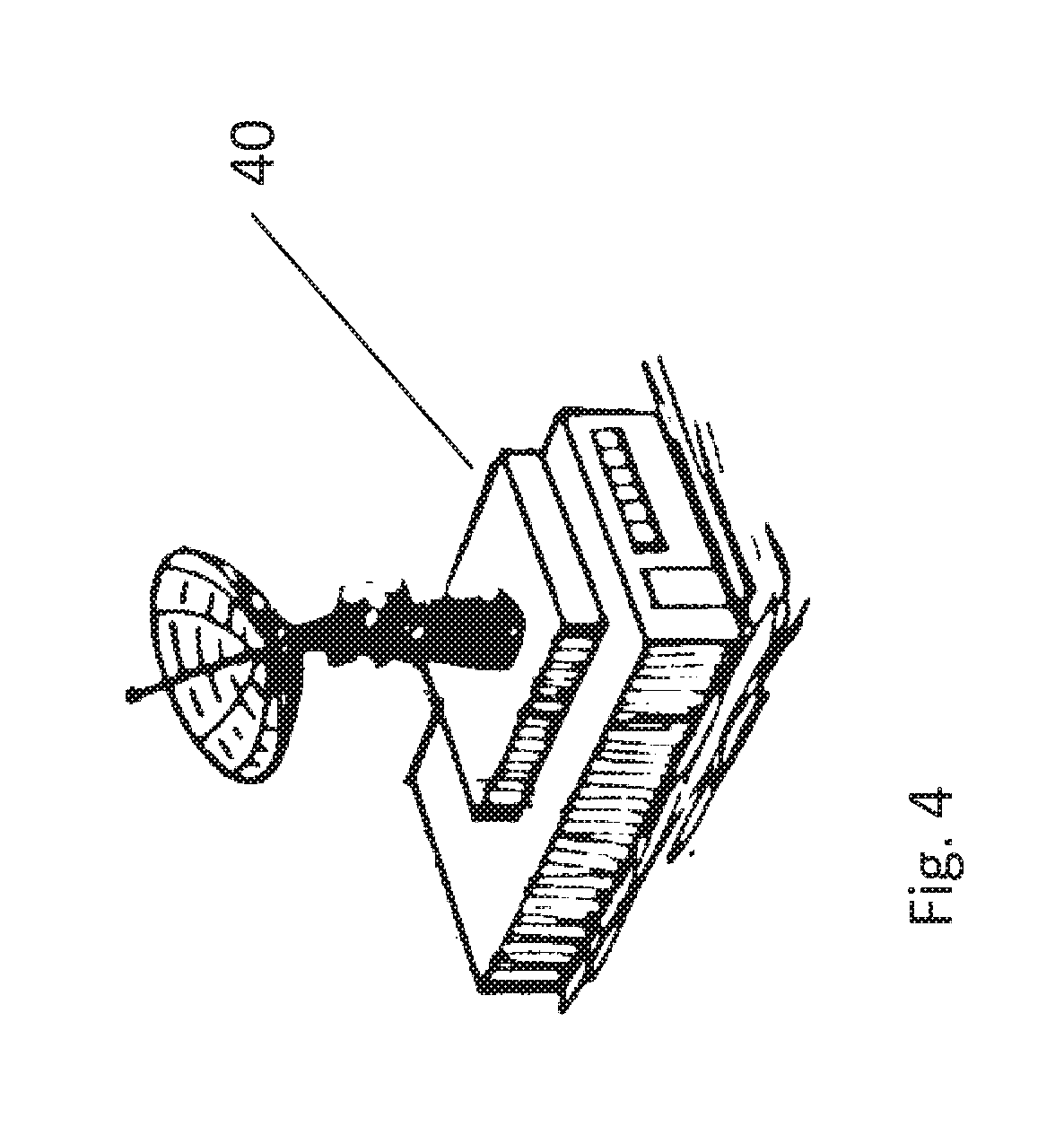
[0048]Forming a sign in space is a challenging undertaking, and the present embodiments may provide a practical and economic solution compared to the existing art. Nano-satellite technology is now capable of providing formation flight of multiple nanosatellites.

[004...


PUM


Abstract

A nanosatellite with an illumination element, and an arrangement of nanosatellites in low earth orbit (LEO) arranged to controllably apply their illumination to be visible on the ground. The nanosatellites may be coordinated to provide illumination events visible on the ground at particular locations and particular times.

Description

RELATED APPLICATIONS[0001]This application claims the benefit of priority under 35 USC 119(e) of U.S. Provisional Patent Application Nos. 62 / 126,860 filed on Mar. 2, 2015 and 62 / 127,351 filed on Mar. 3, 2015. The contents of the above applications are all incorporated by reference as if fully set forth herein in their entirety.FIELD AND BACKGROUND OF THE INVENTION[0002]The present invention, in some embodiments thereof, relates to displays in space that are observable from the ground, and, more particularly, but not exclusively, to a satellite and control arrangement to provide such a display.[0003]There have been proposals for creating signs in space that would be visible from the ground, for example—for advertising purposes.[0004]Known solutions require large satellites and expensive (heavy) deployment mechanisms and resources.[0005]An example of the existing art is US Patent Application No. 2012 / 0223189 published Sep. 12, 2012 of Hitoshi Kuninaka, which relates to an apparatus an...

Claims


Application Information

Patent Timeline
Patent Type & Authority Applications(United States)
IPC IPC(8): B64G1/10B64G1/24F21V7/00F21V14/02F21S9/03F21V23/00
CPCB64G1/1085F21S9/03F21V23/003F21Y2101/02F21V14/02B64G1/24F21V7/00B64G1/10B64G1/425B64G1/64B64G1/66B64G1/222B64U2201/102B64G1/643B64U2201/20B64U2101/75
Inventor SHMUELI, ODEDBEHAR, EHUD
Owner TECHNION RES & DEV FOUND LTD
Features
  • R&D
  • Intellectual Property
  • Life Sciences
  • Materials
  • Tech Scout
  • Unparalleled Data Quality
  • Higher Quality Content
  • 60% Fewer Hallucinations
Learn More