Flush toilet apparatus

a technology for flushing toilets and toilets, applied in water installations, lavatory sanities, construction, etc., can solve the problems of difficult to insert supply pipes and power supply cords through holes, and difficulty in forming holes in positions not overlapping with affixing members, and achieves high rigidity of supply pipes

Active Publication Date: 2016-09-08
TOTO LTD
View PDF2 Cites 4 Cited by
  • Summary
  • Abstract
  • Description
  • Claims
  • Application Information

AI Technical Summary

Benefits of technology

[0007]However, in the flush toilet apparatus described above, the high rigidity of the supply pipe means restricts routing of the supply pipe, making it difficult to insert supply pipes and power supply cords through the hole.

Problems solved by technology

However, in the flush toilet apparatus described above, the high rigidity of the supply pipe means restricts routing of the supply pipe, making it difficult to insert supply pipes and power supply cords through the hole.
Therefore as the compactifying of flush toilet apparatuses proceeds, the problem has arisen that forming a hole in a position not overlapping with an affixing member has become difficult.

Method used


Image

  • Flush toilet apparatus
  • Flush toilet apparatus
  • Flush toilet apparatus

Examples


first embodiment

[0045]Below, referring to the attached drawings, we explain a flush toilet apparatus according to the invention.

[0046]First, referring to FIGS. 1 and 2, we explain the basic structure of a flush toilet apparatus according to the present embodiment.

[0047]FIG. 1 is a perspective view showing a flush toilet apparatus according to a first embodiment of the invention; FIG. 2 is a side view showing a flush toilet apparatus according to a first embodiment of the invention.

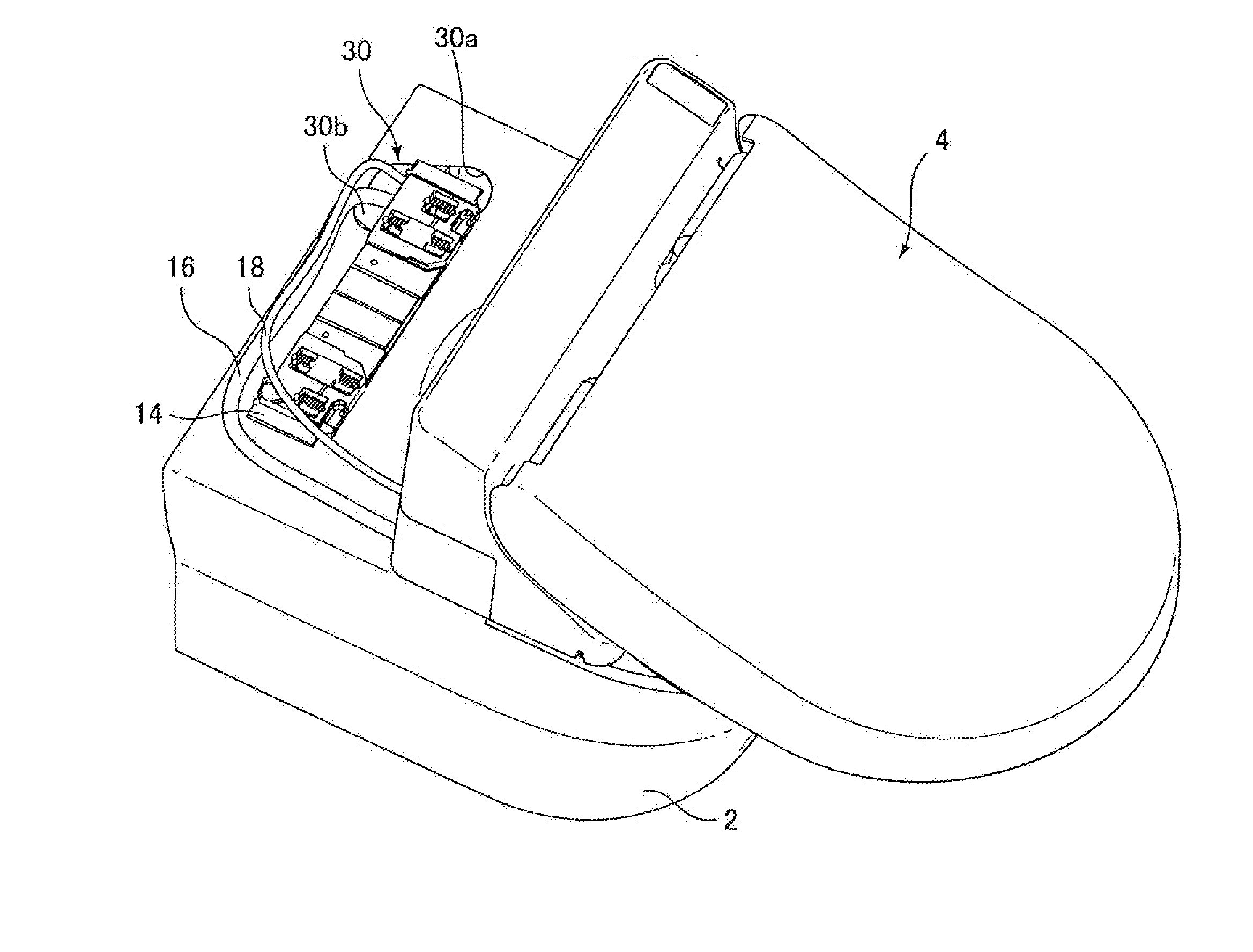
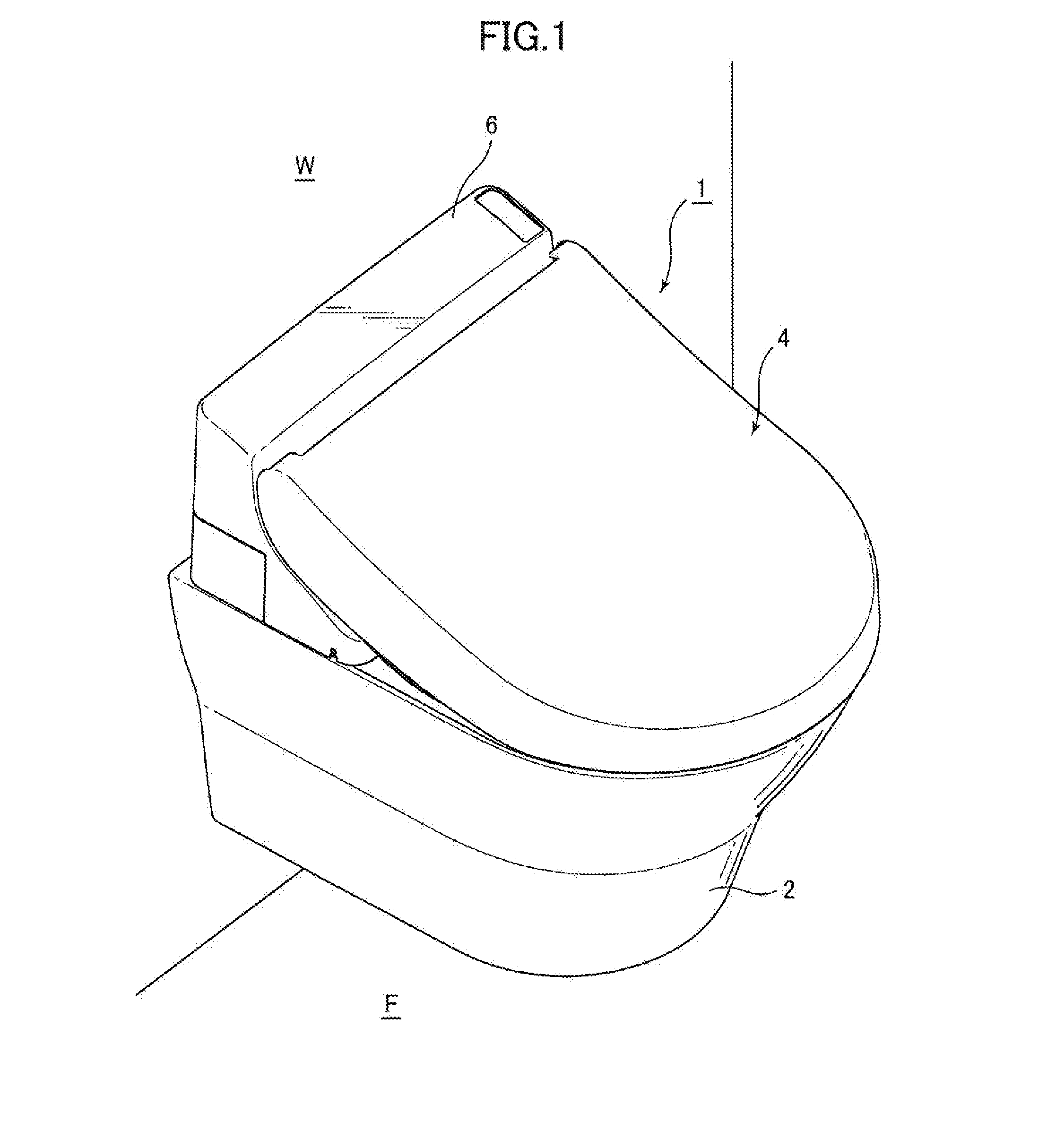
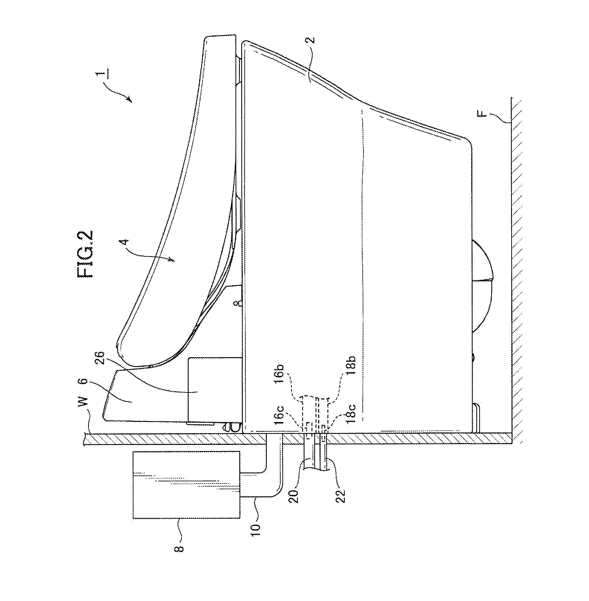
[0048]As shown in FIG. 1, a flush toilet apparatus 1 includes a toilet main body 2 and a washing apparatus 4 attached to this toilet main body 2.

[0049]The toilet main body 2 includes a bowl portion 2a; the bowl portion 2a is flushed with flush water so that waste is discharged.

[0050]In addition, the washing apparatus 4 has a functional portion 6 comprising a flush nozzle (not shown), a nozzle drive motor (not shown), a motor control device (not shown), and the like; a user's anal area is washed by anal area-washing flush ...

second embodiment

[0093]Next, referring to FIG. 8, we explain a flush toilet apparatus according to the invention.

[0094]FIG. 8 is a plan view of a flush toilet main body in a flush toilet apparatus according to a second embodiment of the invention.

[0095]Note that in a flush toilet 100 according to the embodiment of the invention shown in FIG. 8, those parts which are the same as parts of the flush toilet apparatus 1 according to the first embodiment shown in FIGS. 1 through 7 are assigned the same reference numerals, and an explanation thereof is here omitted.

[0096]As shown in FIG. 8, in a flush toilet apparatus 1 according to a second embodiment of the invention the hole portion 130 for passing the water supply pipe 16 and electrical cable 18 connected to the washing apparatus 4 from the upper part of the toilet main body 2 through the interior of the toilet main body 2 is positioned further to the rear than the bowl portion 2a on the toilet main body 2, and is disposed to the left side of the cente...


PUM


Abstract

A flush toilet apparatus includes a hole wherein a tubular member is connected to a connecting portion disposed on the outside of a flush toilet apparatus through a hole portion formed at the rear top surface of a flush toilet main body, and the hole portion comprises a hole penetrating the entire wall thickness of the flush toilet main body; and an guiding path disposed adjacent to the hole, for guiding the tubular member to the hole; wherein at least a portion of the hole of the hole portion is covered by an affixing member, and the tubular member is inserted into the hole through the gap formed between the affixing member and the guiding path.

Description

BACKGROUND OF THE INVENTION[0001]1. Technical Field[0002]The present invention pertains to a flush toilet apparatus, and more particularly to a flush toilet apparatus in which part of a tubular member is housed inside the flush toilet main body.[0003]2. Description of Related Art[0004]For some time, as described for example in Patent Document 1 (Japanese Patent Unexamined Publication No. 2014-147445), flush toilet apparatuses have been known in which a washing apparatus (sanitary washing apparatus) housing a functional portion for anal area washing is affixed relative to an affixing member affixed at the rear top surface of the flush toilet main body.[0005]In such flush toilet apparatuses, when tubular members such as water supply pipes or power supply cords connected to a washing apparatus are in turn connected to water supply connections or power supply connection on a wall, the tubular members such as supply pipes or power supply cords are housed inside the flush toilet main body...

Claims


Application Information

Patent Timeline
Patent Type & Authority Applications(United States)
IPC IPC(8): E03D9/08
CPCE03D9/08
Inventor SHIRAISHI, MASATERUKOGA, MITSUOYAMAZAKI, SATOSHITSUJI, KOHEI
Owner TOTO LTD
Why Eureka
Try Eureka