Modular concrete fence system

Inactive Publication Date: 2016-09-08
MARSHALL DALE R
View PDF3 Cites 0 Cited by
  • Summary
  • Abstract
  • Description
  • Claims
  • Application Information

AI Technical Summary

Benefits of technology

The present fencing system has a plurality of panel modules with a central panel and semicolumnar projections that have a slot for a support column. The system also includes one or more connection brackets that can be fixed to the panel modules to extend into an internal cavity for supporting a substantially rigid ground-engaging support column. The engagement element of the connection bracket can engage the interior walls of the open end of the support column through threaded elements or jam nuts to adjust the vertical alignment of the panel module. The fencing system also includes a lower bracket to retain and align the semicolumnar projections adjacent to the support column. The technical effects of the invention include a simplified fencing system that allows for easy assembly and adjustment of the vertical alignment of panel modules.

Problems solved by technology

This requirement limits flexibility during the assembly process, as it may not be easy or even possible to independently assemble sections of the fence which are separate from each other, and to connect the individual sections later by adding panels between the sections.
Furthermore, it can be difficult and costly to replace a damaged panel in the middle of a fencing run.

Method used


Image

  • Modular concrete fence system
  • Modular concrete fence system
  • Modular concrete fence system

Examples


Embodiment Construction

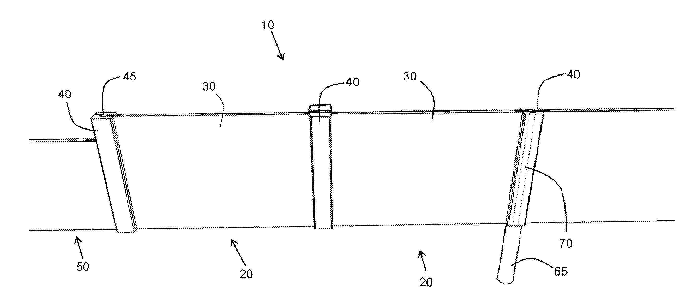
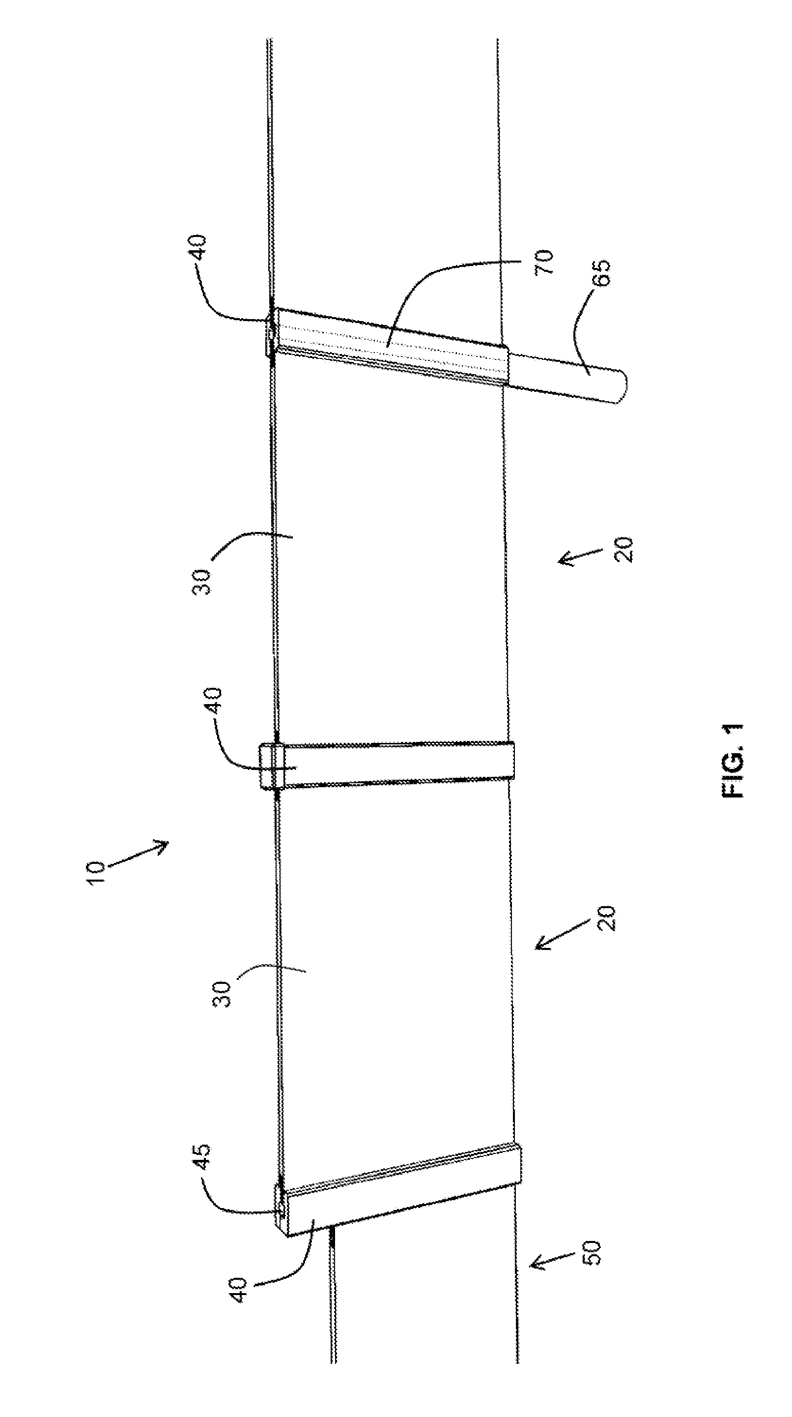
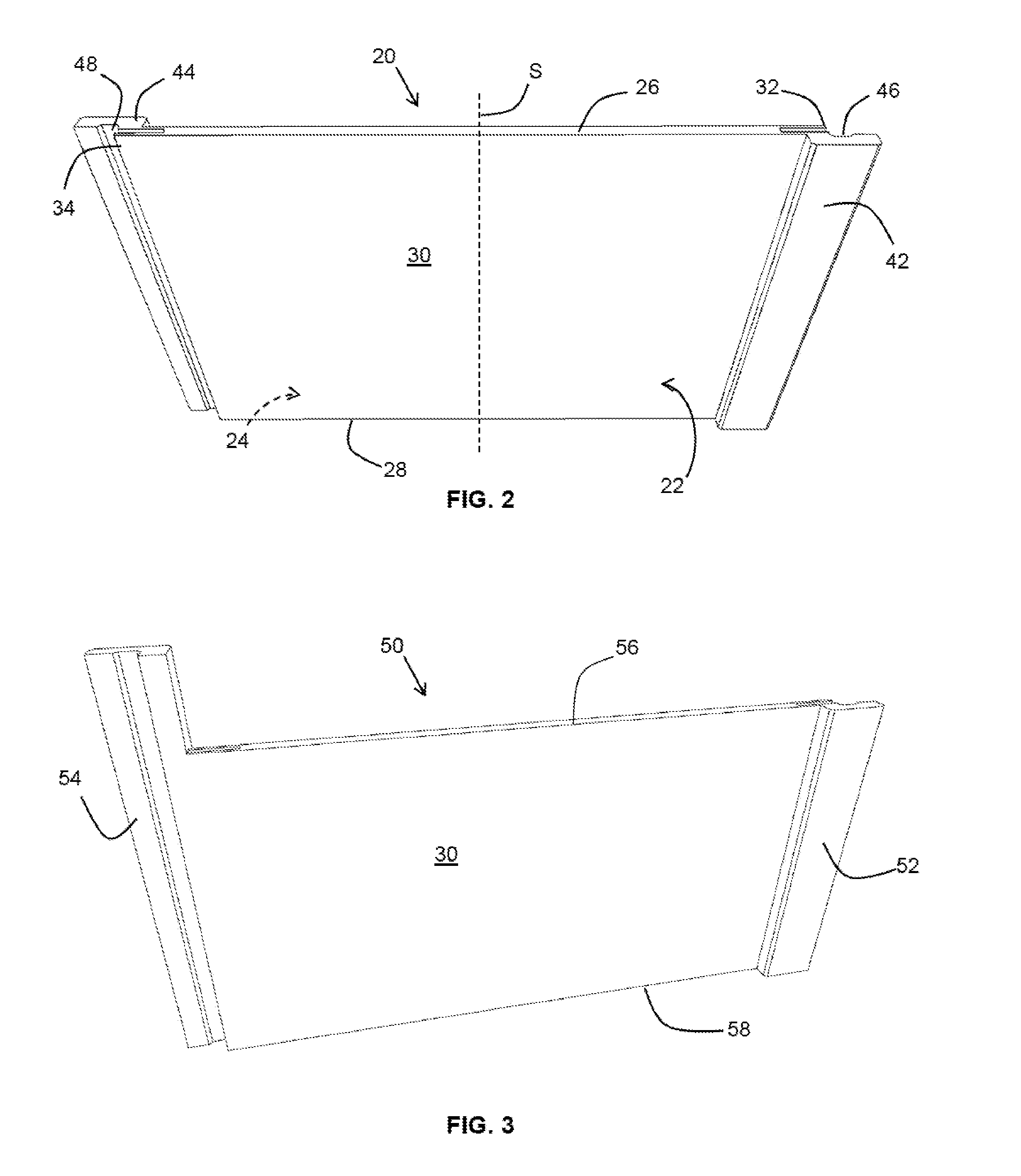
[0020]Specific illustrative and non-limiting embodiments of the present fencing system will now be described with reference to the Figures.

[0021]As used herein, the term “substantially” refers to the complete or nearly complete extent or degree of an action, characteristic, property, state, structure, item, or result. For example, an object that is “substantially” aligned would mean that the object is either completely aligned or nearly completely aligned. The exact allowable degree of deviation from absolute completeness may in some cases depend on the specific context. However, generally speaking the nearness of completion will be so as to have the same overall result as if absolute and total completion were obtained.

[0022]The use of “substantially” is equally applicable when used in a negative connotation to refer to the complete or near complete lack of an action, characteristic, property, state, structure, item, or result. For example, a composition that is “substantially free ...


PUM


Abstract

The present fencing system includes panel modules having a substantially planar central panel with semicolumnar projections extending at either side. The semicolumnar projections each have a longitudinal slot extending between the top edge and the bottom edge, such that two adjacent panel modules overlap to form a column element having an internal cavity. A support column secured to the ground is received within the internal cavity formed by the longitudinal slots of overlapping semicolumnar projections. One or more connection brackets fixed to the panel module engage the support column to hold the panel modules in place.

Description

BACKGROUND OF THE INVENTION[0001]The present invention relates to fences, and specifically to a modular fencing system including pre-cast concrete panels.[0002]Concrete fences and walls find many applications for outdoor use in landscaping, or as sound barriers to protect residents near noisy highways and airports. Modular fence and wall systems including pre-formed panels are known. Such systems are often assembled from modular panels which are connected by fitting a protrusion on an end of one panel or column into a recess in an end of an adjacent panel or column. For example, U.S. Pat. No. 7,802,409, U.S. Pat. No. 6,827,336, U.S. Pat. No. 5,887,404, U.S. Pat. No. 5,373,678 and US Patent Application Publication 2010 / 0314596 describe such systems. However, such fencing systems need to be assembled progressively from one end so that the end of a newly added panel can connect properly to previously placed panels. This requirement limits flexibility during the assembly process, as it ...

Claims


Application Information

Patent Timeline
IPC IPC(8): E04H17/16E04C2/04E04H17/20
CPCE04H17/168E04H2017/1447E04C2/044E04H17/20E04H17/1447E04H17/21E04H17/17
Inventor MARSHALL, DALE R.
Owner MARSHALL DALE R
Why Eureka
Try Eureka