Display Apparatus

a technology of display apparatus and display plate, which is applied in the direction of optical light guide, instruments, optics, etc., can solve the problems of insufficient narrowing of the border width, damage to the display plate, and warpage of the guide plate, so as to prevent expansion or deflection, uniform white light, and low transmittance to light in the long wavelength region

Active Publication Date: 2016-09-08
SAKAI DISPLAY PROD
View PDF11 Cites 11 Cited by
  • Summary
  • Abstract
  • Description
  • Claims
  • Application Information

AI Technical Summary

Benefits of technology

[0031]According to the present invention, the outer periphery of the frame body placed between the liquid-crystal panel and the transparent plate has a shape along an entire circumference of an outer peripheral edge of a wide surface of the glass substrate or the transparent plate having substantially the same shape. This facilitates the glass substrate and the transparent plate to be integrally formed, while enabling the inner side of the frame body to be made wider.
[0032]According to the present invention, the outer periphery of the frame body plated between the liquid-crystal panel and the transparent plate is substantially equal to the outer periphery of the wide surface, having substantially the same shape, of the glass substrate and the light guide plate. This facilitates the glass substrate and transparent plate to be integrally formed, while enabling the inner side of the frame body to be made wider.
[0033]According to the present invention, in accordance with the use of the transparent plate made of glass for the light guide plate, such a configuration is adopted that a blue light emitting diode not applied with a fluorescent material is used as a light source opposed to a part of the peripheral surface of the light guide plate or to a surface of the transparent plate opposite to the liquid-crystal panel, and a sheet added with a fluorescent material emitting fluorescent light having a wavelength longer than a wavelength of blue light is included or the fluorescent material is applied to the light guide plate. Glass has non-uniform transmittance to light in the visible light region across all the different wavelengths, the transmittance to the light in the long wavelength region being particularly low. Therefore, the configuration in which a sheet added with a fluorescent material is further used or a fluorescent material is applied allows emission of light on the long wavelength side between the light guide plate and the liquid-crystal panel, making it possible to irradiate the liquid-crystal panel with uniform white light.
[0034]According to the present invention, a gel-like or liquid-like translucent material having a refractive index lower than that of the optical sheet is filled into the frame body which is placed between the liquid-crystal panel and the transparent plate and which accommodates the optical sheet therein. This can prevent expansion or deflection caused by the optical sheet absorbing moisture from the air in the display apparatus.
[0035]According to the present invention, the transparent plate used as the light guide plate is made of glass which has relatively high rigidity and is insusceptible to thermal expansion. This enables the transparent plate to be used as a basis to position other components in the display apparatus, which thus can easily realize a curved display having a transparent plate of a curved plate similar to the liquid-crystal panel.
[0036]According to the present invention, holding members for a light guide plate and an optical sheet used in conventional display apparatus is unnecessary, making display product much thinner. Moreover, a holding member having larger outer shape than a liquid-crystal panel is unnecessary, so that frame width can be narrowed.

Problems solved by technology

It is, however, insufficient in narrowing of border width since the protection plate and light guide plate are made larger than the liquid-crystal panel.
This will not be a problem in a small display apparatus, but may cause problems in a large display apparatus as the size difference would be larger in a large display apparatus, possibly causing separation of the protection plate from the light guide plate or causing the light guide plate to warp when the bonding strength is high, which may damage the apparatus.

Method used


Image

  • Display Apparatus
  • Display Apparatus
  • Display Apparatus

Examples


embodiment 1

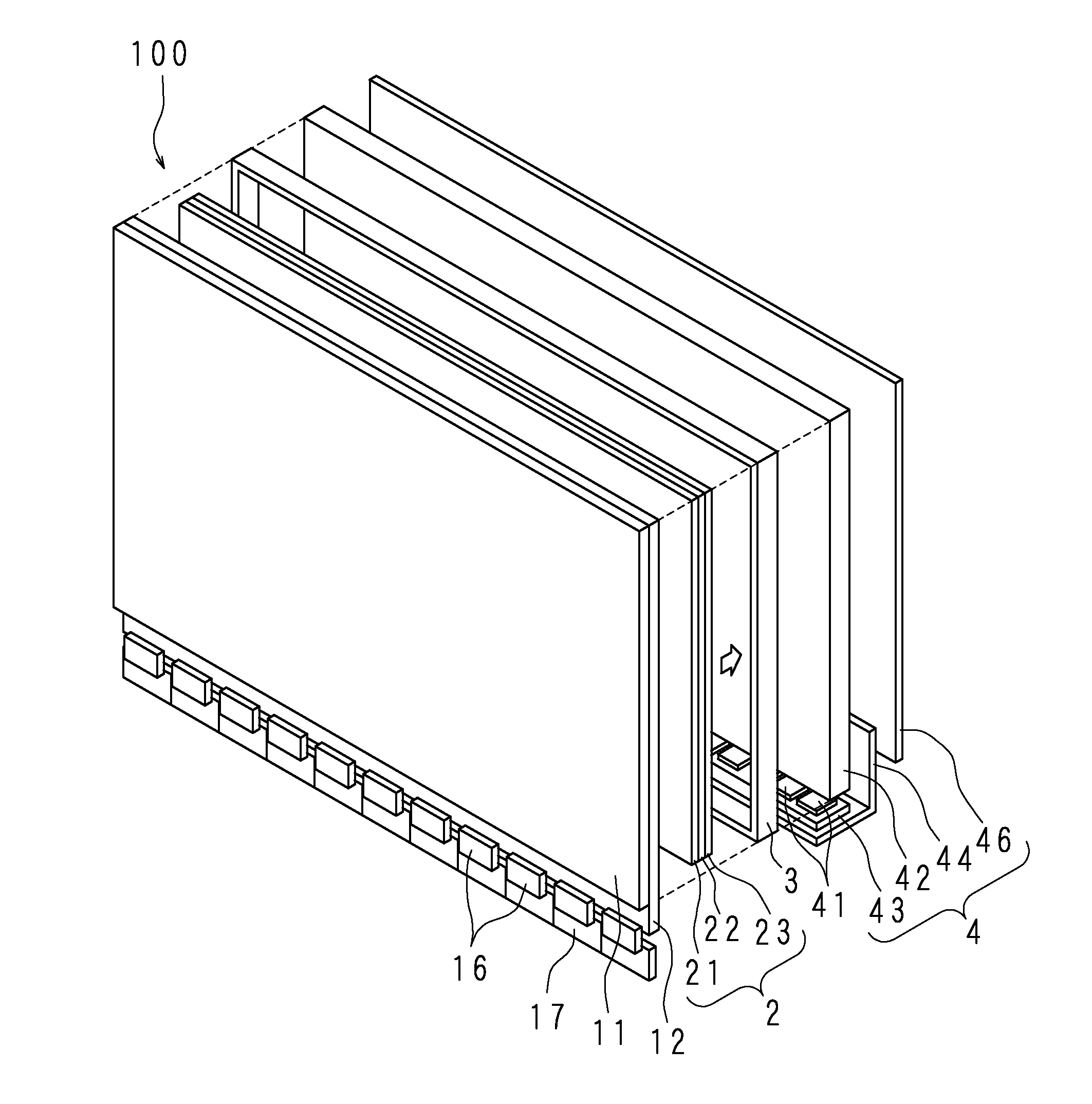
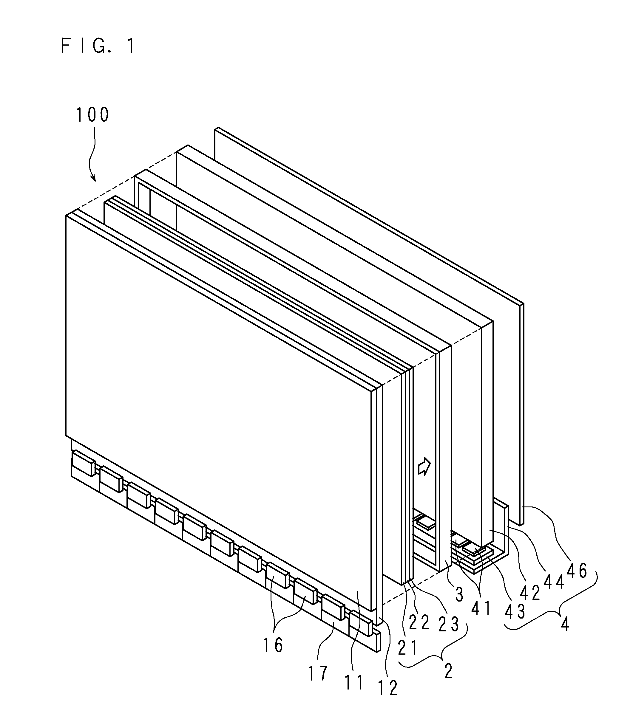
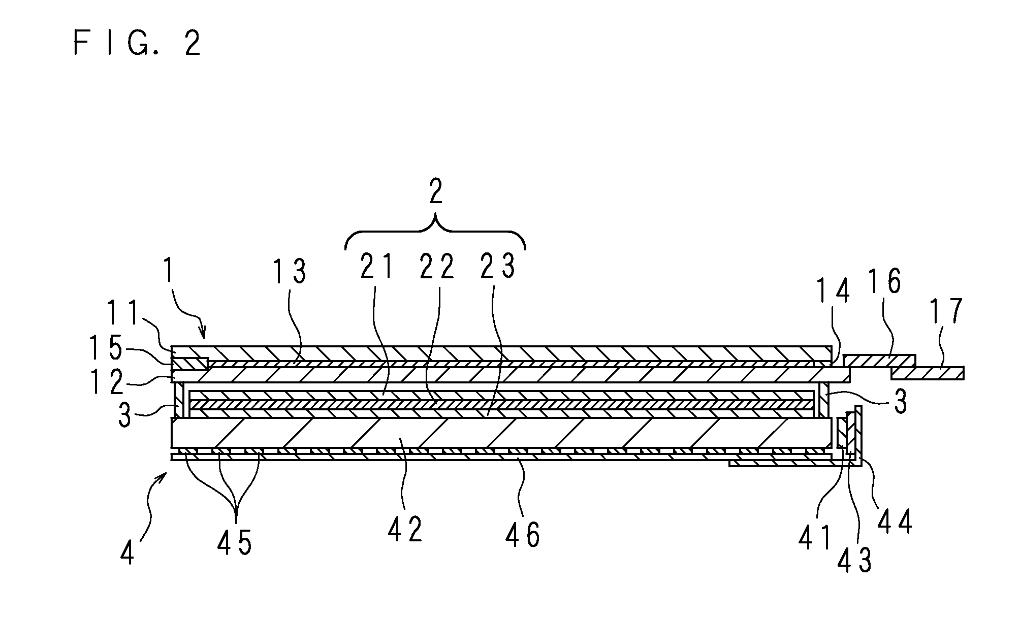
[0046]FIG. 1 is an exploded perspective view schematically illustrating the main parts of a display apparatus 100 according to Embodiment 1, and FIG. 2 is a cross section schematically illustrating the main parts of the display apparatus 100. The display apparatus 100 includes a liquid-crystal panel 1 and a light source device 4.

[0047]The liquid-crystal panel 1 is a display panel having a shape of a rectangular flat plate. The liquid-crystal panel 1 employs an active matrix system. The liquid-crystal panel 1 is so configured that liquid crystal 13 is injected between two glass substrates 11 and 12 arranged to be opposed to each other with a predetermined distance in between, and is sealed with seal materials 14, 15. In pixel regions at the middle parts of the glass substrates 11, 12, various elements (not illustrated) are formed including an electrode for driving the liquid crystal 13. The liquid-crystal panel 1 includes, at an end on one long side of one glass substrate 12, a drive...

embodiment 2

[0057]FIG. 5 is a cross section schematically illustrating the main parts of the display apparatus 100 according to Embodiment 2. The configuration of the display apparatus 100 according to Embodiment 2 is similar to the configuration of the display apparatus 100 according to Embodiment 1, except for a part which will be described below. The common configuration parts are therefore denoted by the same reference numerals and will not be described in detail.

[0058]The optical sheet 2 according to Embodiment 2 includes, in addition to the lens sheet 21, prism sheet 22 and diffusion sheet 23, a fluorescent sheet 24 which is added with multiple types of fluorescent materials emitting fluorescent light of a wavelength on a side of a wavelength longer than that of blue, i.e. a wavelength in the range from green to red.

[0059]Furthermore, in the light source device 4 according to Embodiment 2, a blue light-emitting diode 47 which is not applied with a fluorescent material on its surface is us...

embodiment 3

[0062]FIG. 6 is a cross section schematically illustrating the main parts of the display apparatus 100 according to Embodiment 3. The configuration of the display apparatus 100 according to Embodiment 3 is similar to the configuration of the display apparatus 100 according to Embodiment 1, except for a part which will be described below. The common configuration parts are therefore denoted by the same reference numerals and will not be described in detail.

[0063]In the display apparatus 100 according to Embodiment 3, the frame body 3 in which the optical sheet 2 is sealed is filled with gel or liquid translucent material 31 having a refractive index lower than that of the optical sheet 2.

[0064]According to Embodiment 3, after the frame body 3 is placed on the light guide plate 42 at the time of assembly and the optical sheet 2 is accommodated therein, the translucent material 31 is filled into the frame body 3, and the liquid-crystal panel 1 is so placed as to cover the frame body 3....


PUM

PropertyMeasurementUnit
transparentaaaaaaaaaa
wavelengthaaaaaaaaaa
refractive indexaaaaaaaaaa

Abstract

Provided is a display apparatus having a structure capable of realizing reduction in thickness and border width.
A display apparatus having a liquid-crystal panel prepared by enclosing a liquid-crystal material between a pair of glass substrates opposing to each other, a transparent plate opposed to the liquid-crystal panel, and an optical sheet arranged between the liquid-crystal panel and the transparent plate, and having a face smaller than the liquid-crystal panel, wherein the transparent plate is a glass plate having a wide surface of substantially a same shape as a wide surface of each of the glass substrate, and the display apparatus further comprises a frame body arranged between the liquid-crystal panel and the transparent plate, the frame body surrounding an outer periphery of the optical sheet, the frame body being thicker than the optical sheet.

Description

[0001]This application is the national phase under 35 U.S.C. §371 of PCT International Application No. PCT / JP2014 / 055891 which has an International filing date of Mar. 7, 2014 and designated the United States of America.BACKGROUND OF THE INVENTION[0002]1. Field of the Invention[0003]The present invention relates to a display apparatus using a liquid-crystal panel, and more particularly to a display apparatus having a configuration capable of further realizing reduction in thickness and border width of the apparatus.[0004]2. Description of Related Art[0005]A display apparatus using a liquid-crystal panel includes a light source, and also includes an optical sheet for diffusing or condensing light from the light source between the light source and the liquid-crystal panel. For a light source in a recent display apparatus, in order to reduce the thickness of the display apparatus and to suppress unevenness in luminance, an edge light type is frequently used in which multiple light emit...

Claims


Application Information

Patent Timeline
Patent Type & Authority Applications(United States)
IPC IPC(8): F21V8/00G02F1/1341G02F1/1333G02F1/133
CPCG02B6/0088G02F1/13306G02F1/1341G02F2001/133302G02B6/005G02B6/0011G02B6/0065G02F1/133308G02B6/0043G02B6/0068G02F1/133615G02F1/133317G02F1/133614G02F1/133302G02F1/133314
Inventor NEGORO, KAZUHIKO
Owner SAKAI DISPLAY PROD
Why Eureka
Try Eureka