
Assemblies of solar cells with curved edges

a solar cell and assembly technology, applied in the field of discrete solar cells, can solve the problems of increasing the overall cost of the photovoltaic array or panel, inefficient use of the surface on which the solar cell is mounted, and inefficient use of the available space, so as to maximize the packing factor of the solar cell assembly, increase the packing factor, and maximize the packing factor

Inactive Publication Date: 2016-09-08
SOLAERO TECH CORP
View PDF3 Cites 3 Cited by
  • Summary
  • Abstract
  • Description
  • Claims
  • Application Information

AI Technical Summary

Benefits of technology

This patent describes a method for packing solar cells in a way that maximizes the use of the wafer material. By dividing a circular solar cell wafer into semicircles and adding straight portions to them, the number of waste parts can be minimized. The resulting solar cell array has a high packing factor and utilizes more of the wafer material. This method can also be applied to solar cells that are shaped like sectors of a circle, further minimizing waste and achieving a high packing factor.

Problems solved by technology

Arrays of substantially circular solar cells are known to involve the drawback of inefficient use of the surface on which the solar cells are mounted, due to space that is not covered by the circular solar cells due to the space that is left between adjacent solar cells due to their circular configuration (cf.
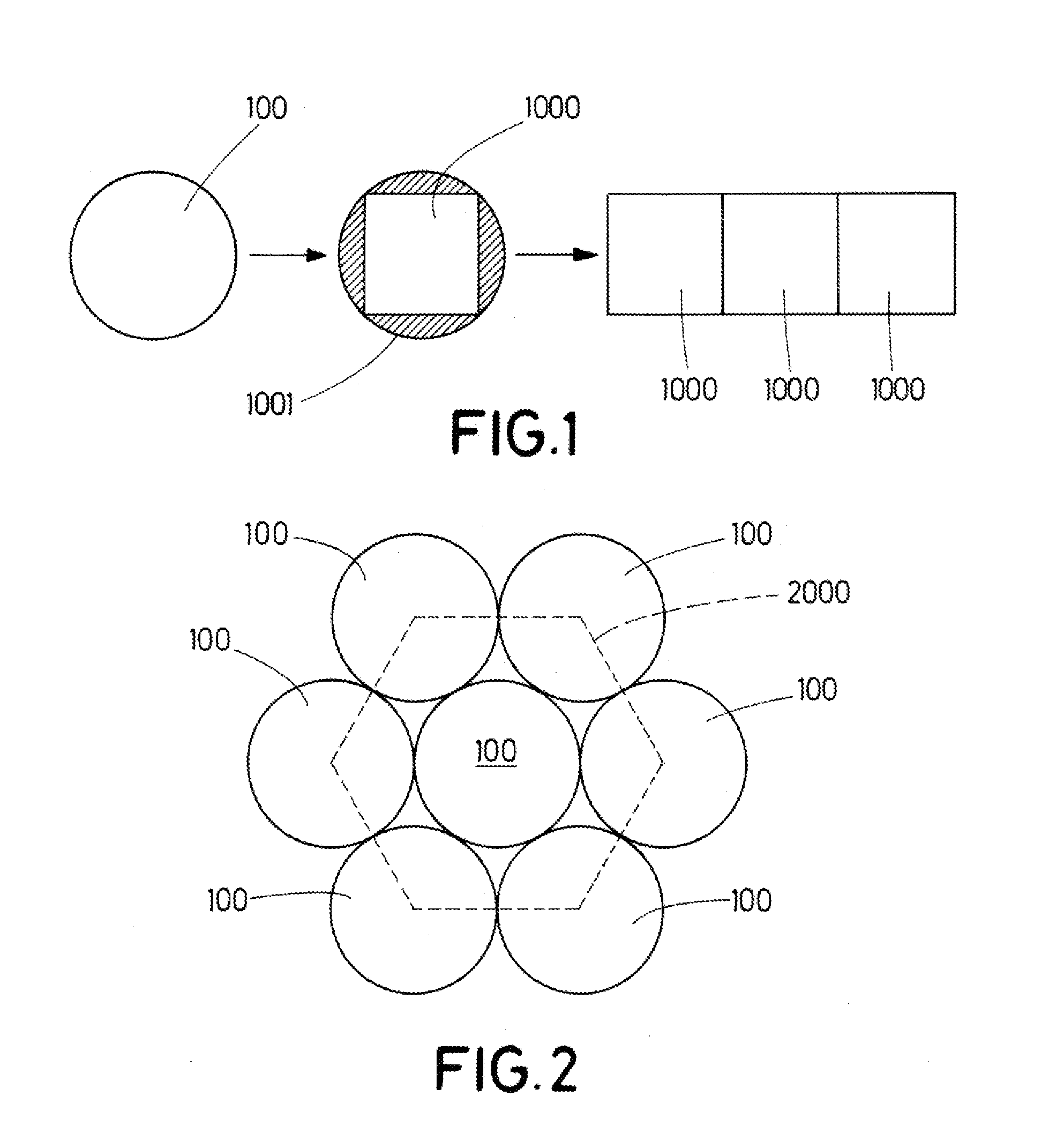
However, as explained above, for assembly into a solar array (henceforth, also referred to as a solar cell assembly), substantially circular solar cells, which can be produced from substantially circular wafers to minimize wasting wafer material and, therefore, minimize solar cell cost, are often not the best option, due to their low array packing factor, which increases the overall cost of the photovoltaic array or panel and implies an inefficient use of available space.
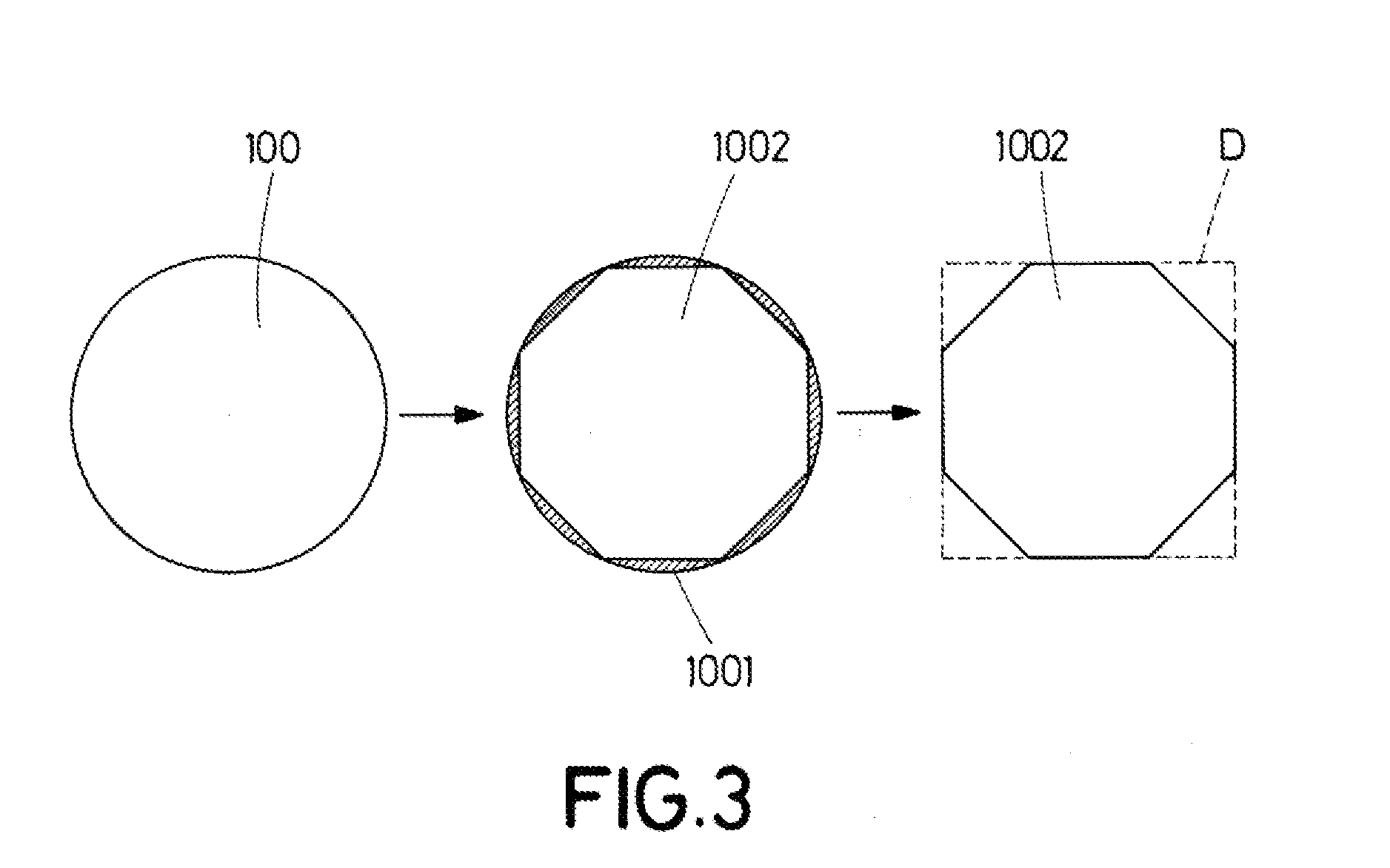
However, when a single circular wafer is divided into a single rectangle, the wafer utilization is low.
This results in waste.
High efficiency solar cell wafers are often costly to produce.
Thus, the waste that has conventionally been accepted in the art as the price to pay for a high packing factor, that is, the waste that is the result of cutting the rectangular solar cell out of the substantially circular solar cell wafer, can imply a considerable cost.
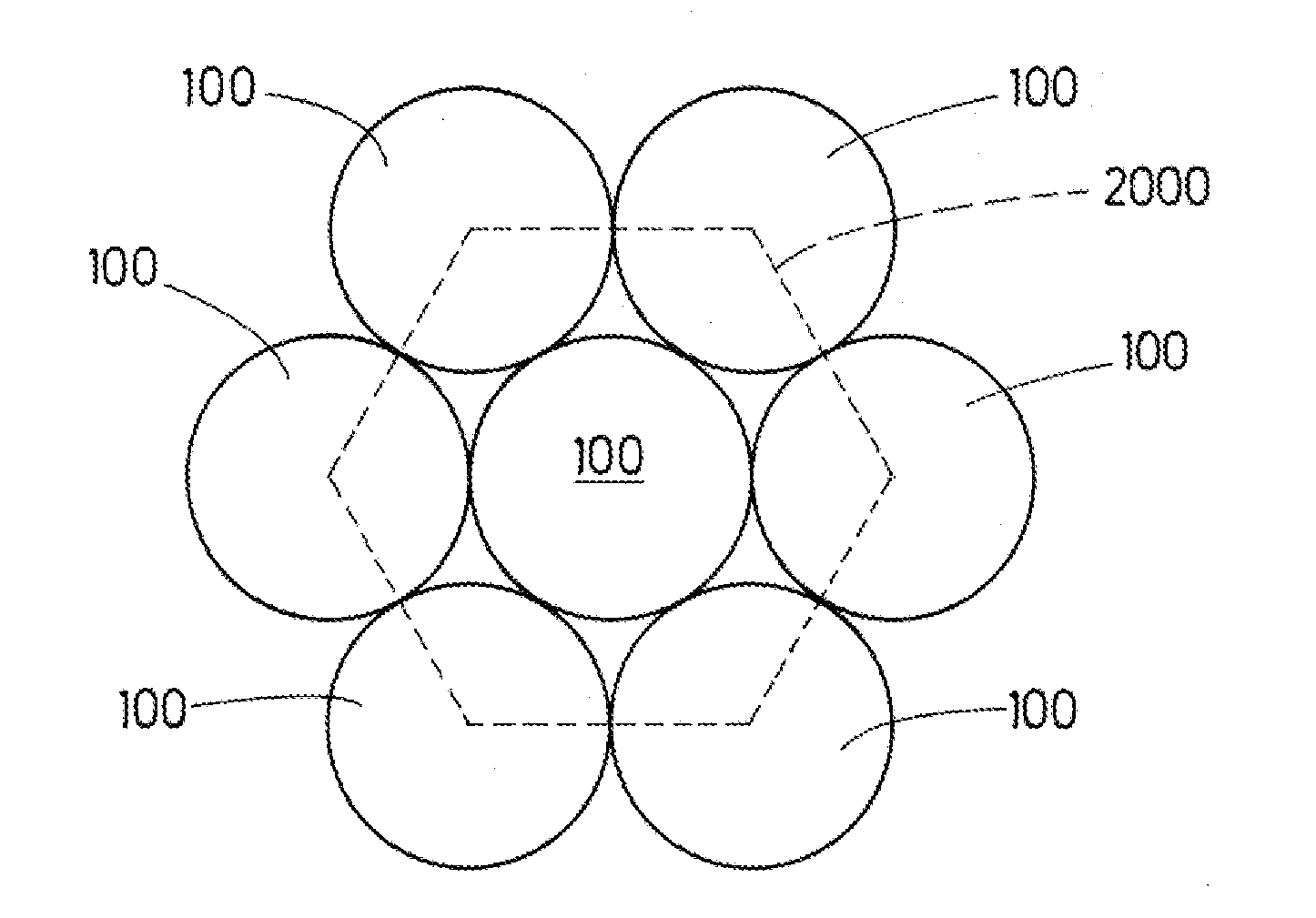
This implies less wafer material is wasted than in the case of the option shown in FIG. 1, but also a less efficient use of the surface on which the solar cells are mounted, due to the lower packing factor.
A further problem is that with this kind of layout, the pattern features a staggered distribution (schematically illustrated by the hexagon 2000 illustrated with broken lines in FIG. 2), which is non-optimal for producing a rectangular assembly of solar cells.
The fact that the different rows of solar cells are staggered in relation to each other means that the assembly of solar cells will not fit neatly to the edges or boundaries of a rectangular panel.
This implies an inefficient use of the space on the panel.

Method used


Image

  • Assemblies of solar cells with curved edges
  • Assemblies of solar cells with curved edges
  • Assemblies of solar cells with curved edges

Examples


Embodiment Construction

[0039]FIG. 4 shows how a substantially circular solar cell wafer 400 with a straight edge portion 401 can be provided with a further straight edge portion 405 by cropping it opposite to the first straight edge portion 401, removing a piece of wafer material 405a.

[0040]In the next step, the wafer is divided into two solar cells 410 and 411, by cutting the wafer in accordance with its diameter, in parallel with the straight edges 401 and 405. Thereby, two substantially identical solar cells 410 and 411 are obtained. Solar cell 410 comprises two parallel straight edges 401 and 402, one of which is longer than the other. The two straight edges 401 and 402 are separated from each other by two curved edges 403 and 404, each corresponding to an arc of the circular edge portion of the original wafer 400. In other embodiments, the wafer can be cut in other ways. It is clear that the surface area of each solar cell 410 and 411 is less than 50% of the surface area of the circle corresponding ...


PUM


Abstract

Solar cells can be obtained by dividing a substantially circular solar cell wafer into portions featuring straight and arcuate edges, which are then combined to form solar cell arrays. The solar cells can be arranged in different ways, for example, with straight edges abutting against straight edges of adjacent solar cells, or with the solar cells in a row having at least one straight edge extending at an angle of between 50 and 70 degrees the direction of the row.

Description

[0001]This application claims the benefit of U.S. Provisional Application No. 62 / 128,132, filed Mar. 4, 2015, which is incorporated herein by reference in its entirety[0002]This application is related to U.S. patent application Ser. Nos. 14 / 498,071 filed Sep. 26, 2014, and 14 / 514,883 filed Oct. 15, 2014.BACKGROUND OF THE DISCLOSURE[0003]1. Field of the Disclosure[0004]The disclosure relates to the field of photovoltaic power devices, and more particularly arrays of discrete solar cells.[0005]2. Description of the Related Art[0006]Photovoltaic devices, such as photovoltaic modules or CIC (Solar Cell+Interconnects+Coverglass) devices, comprise one or more individual solar cells arranged to produce electric power in response to irradiation by solar light. Sometimes, the individual solar cells are rectangular, often square. Photovoltaic modules, arrays and devices including one or more solar cells may also be substantially rectangular, for example, based on an array of individual solar ...

Claims


Application Information

Patent Timeline
Patent Type & Authority Applications(United States)
IPC IPC(8): H01L31/0352H01L31/047H01L31/0304
CPCH01L31/035281H01L31/047H01L31/0304H01L31/042Y02E10/50
Inventor DERKACS, DANIELAIKEN, DANIELMCPHEETERS, CLAYYANG, LEI
Owner SOLAERO TECH CORP
Learn More