Wear plate for box blade

a wear plate and box blade technology, applied in the field of wear plates, can solve the problems of short operational life of wear plates, side walls of box blades being subjected to wear,

Inactive Publication Date: 2016-09-15
CATERPILLAR INC
View PDF0 Cites 2 Cited by
  • Summary
  • Abstract
  • Description
  • Claims
  • Application Information

AI Technical Summary

Benefits of technology

[0005]In another aspect of the present disclosure, a box blade is provided. The box blade includes a frame element comprising a first side, a second side, and a rear side. The box blade also includes a wear plate secured to the first side or the second side and is configured to ride along the ground. The wear plate includes a first surface and a second surface. The first and second surfaces are spaced apart from each other and define a thickness of the wear plate therebetween. The wear plate also includes a plurality of openings formed on the wear plate and communicating with the first and second surfaces thereof. The plurality of openings is posit...

Problems solved by technology

As the box blade rides along the ground, side walls of the box blade may be subjected to wear.
Hence, the ...

Method used


Image

  • Wear plate for box blade
  • Wear plate for box blade
  • Wear plate for box blade

Examples


Embodiment Construction

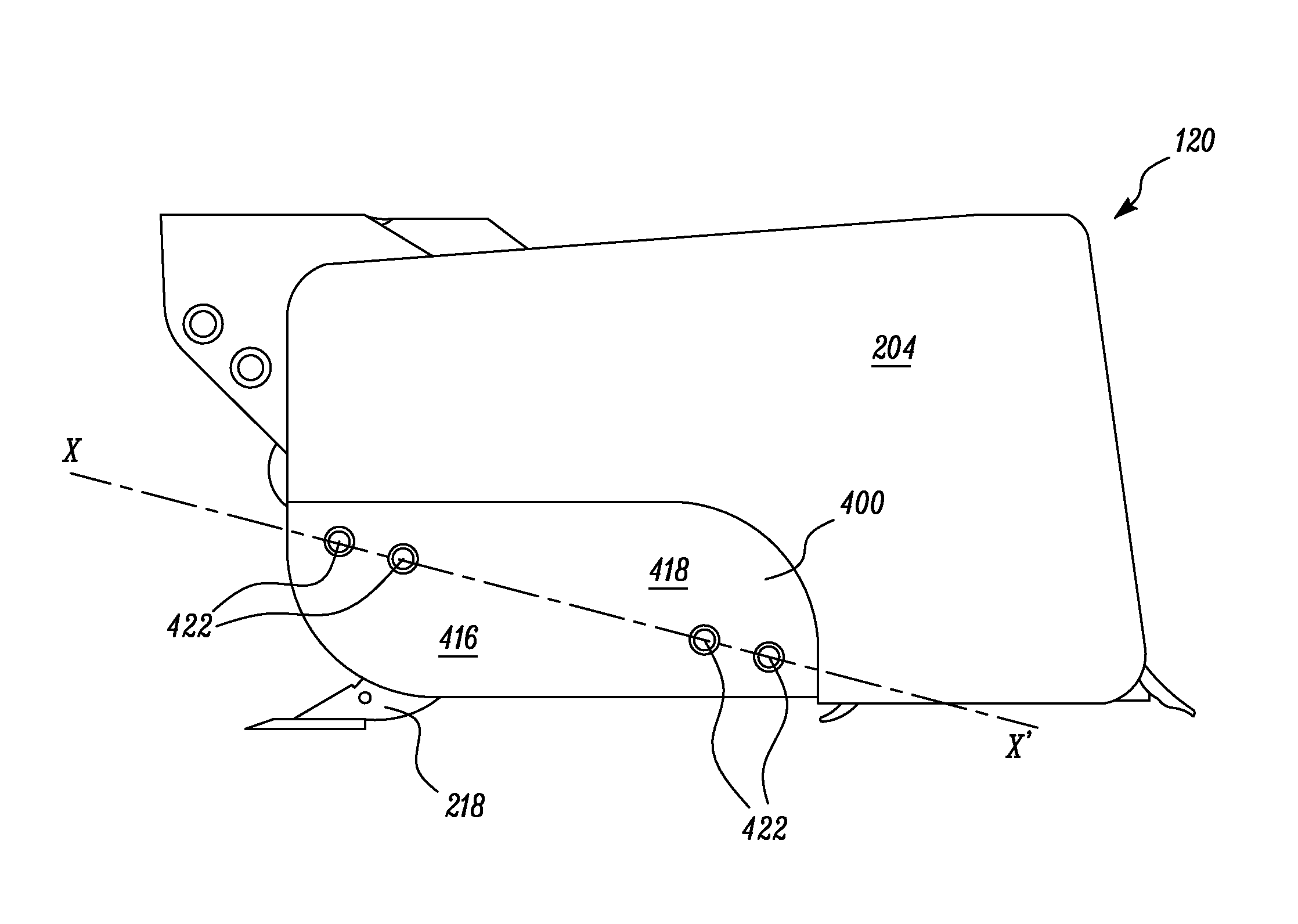
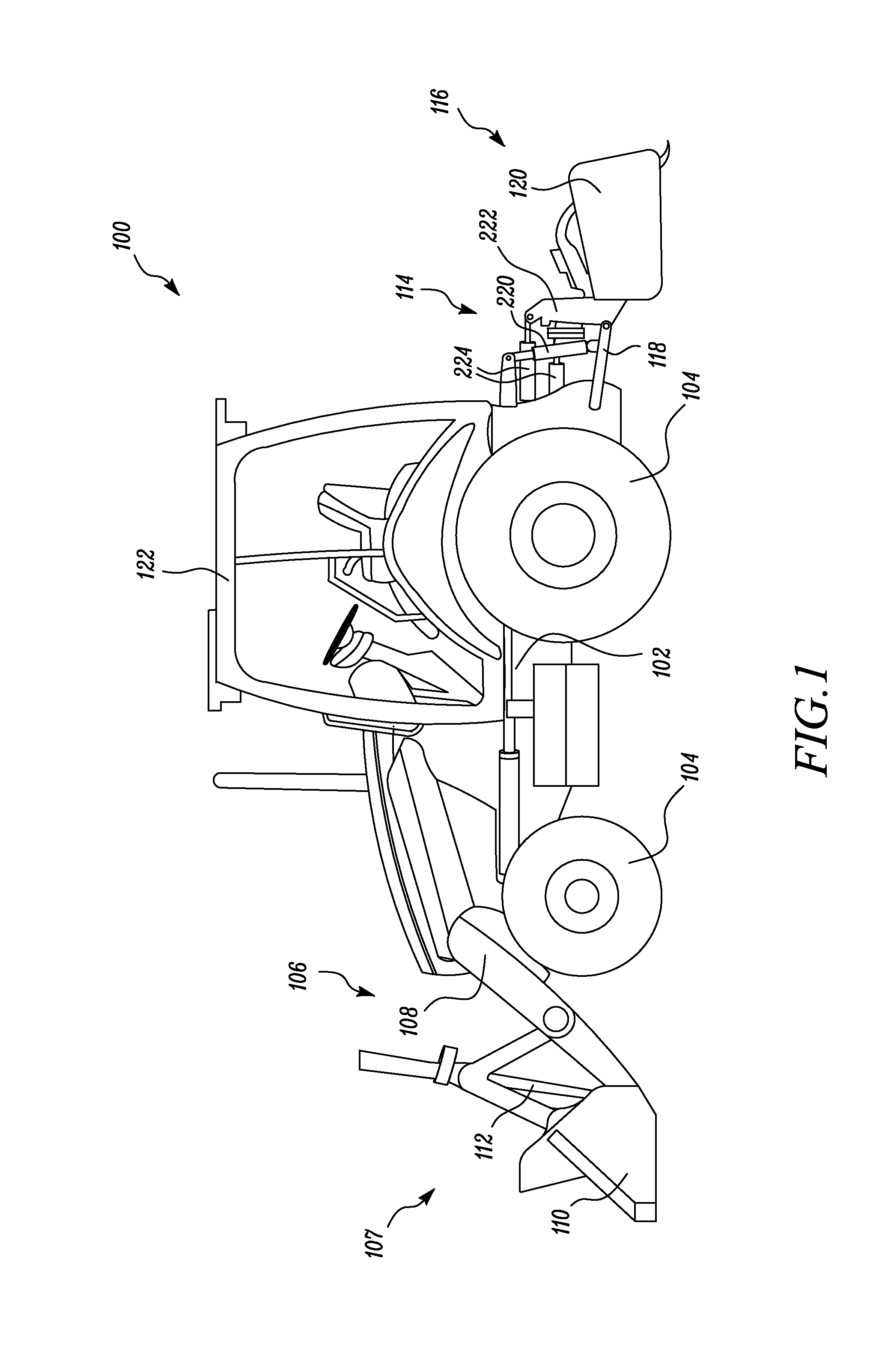
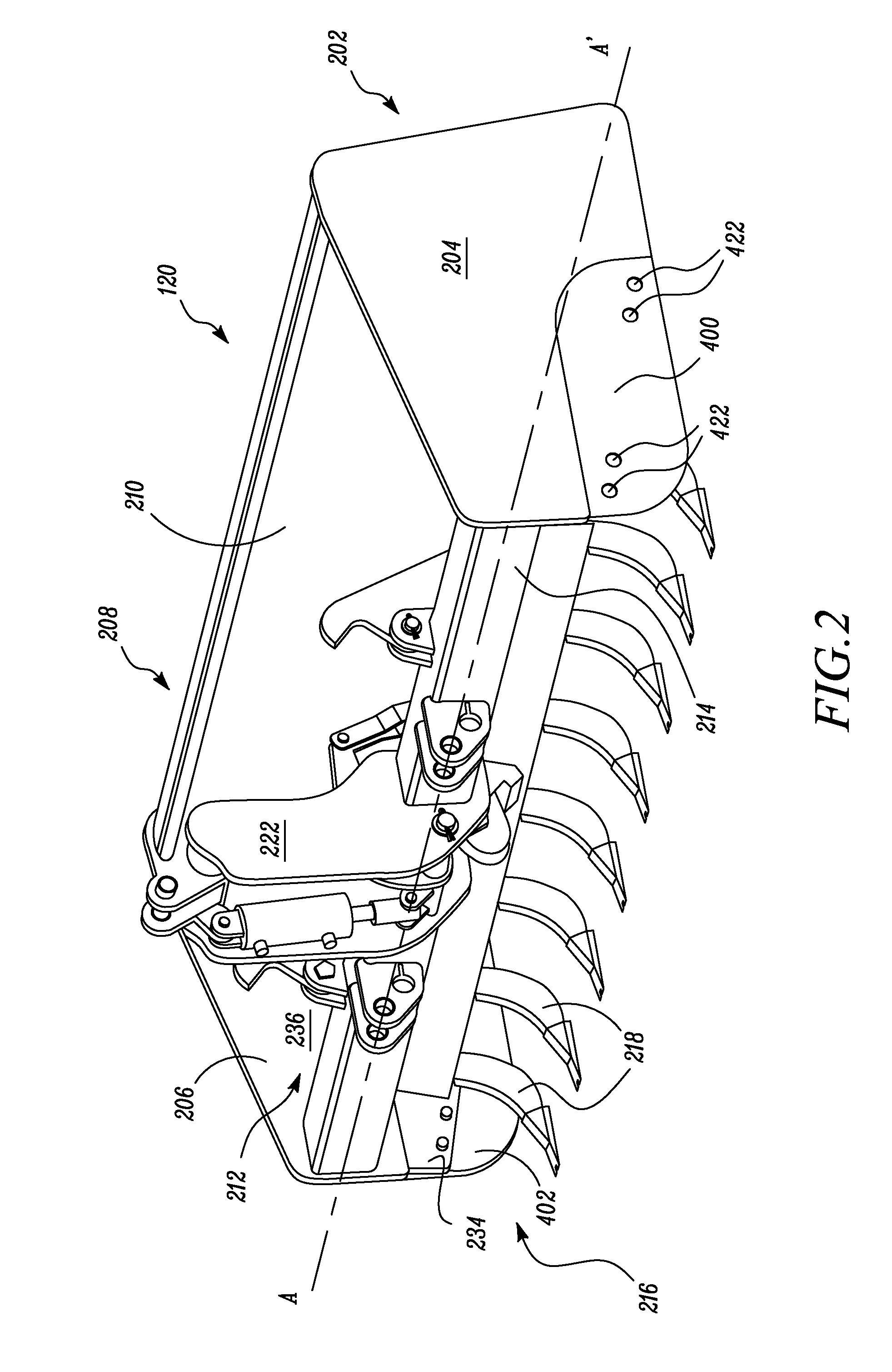
[0018]Wherever possible, the same reference numbers will be used throughout the drawings to refer to the same or the like parts. Referring to FIG. 1, an exemplary machine 100 is illustrated. More specifically, the machine 100 is an industrial loader. Alternatively, the machine 100 may be any machine including, but not limited to, a backhoe loader, a wheel loader, an excavator, a shovel, a dozer, a mining truck, an articulated truck, a track type tractor, a forklift, a crane, skid steer loaders, compact track loaders, multi-terrain loaders, and so on. The machine 100 may be any machine known in the art associated with industries including, but not limited to, agriculture, transportation, mining, construction, forestry, landscaping, and material handling.

[0019]The machine 100 includes a frame 102. A power source (not shown) is provided on the frame 102 of the machine 100. The power source may be any power source known in the art, such as, an internal combustion engine, an electric mot...


PUM


Abstract

A wear plate for a box blade is provided. The wear plate includes a first surface and a second surface. The first and second surfaces are spaced apart from each other and define a thickness of the wear plate therebetween. The wear plate also includes a plurality of openings formed on the wear plate and communicating with the first and second surfaces thereof. The plurality of openings is positioned along a diagonal axis of the wear plate. The plurality of openings is configured to be aligned with corresponding openings formed on a backer plate of the box blade to receive mechanical fasteners therethrough for attaching the wear plate to the backer plate. The wear plate includes a first wear surface defined on one side of the diagonal axis of the wear plate and a second wear surface defined on the other side of the diagonal axis.

Description

TECHNICAL FIELD[0001]The present disclosure relates to a wear plate, and more particularly to a wear plate associated with a box blade of a machine.BACKGROUND[0002]Machines, such as industrial loaders, include a box blade coupled to a rear section of the machine. The box blade is pulled behind the machine, and may be used to scrape, condition, and / or move loose soil or other materials on a ground from one place to another. As the box blade rides along the ground, side walls of the box blade may be subjected to wear. Hence, each side wall of the box blade is provided with a wear plate. The wear plates are subjected to the wear during machine operation, and are designed to be replaced after they wear beyond a certain point. Hence, the wear plates generally have a short operational life as they are subjected to wear during the machine operation.[0003]U.S. Pat. No. 4,869,326, hereinafter referred to as the '326 patent, describes a box scraper for tractors and like vehicles. The box scra...

Claims


Application Information

Patent Timeline
IPC IPC(8): E02F3/815A01B31/00A01B76/00E02F3/76
CPCE02F3/8152A01B76/00A01B31/00E02F3/7622E02F3/961E02F9/2883
Inventor KURIGER, KARL S.RYAN, MICHAEL T.
Owner CATERPILLAR INC
Why Eureka
Try Eureka